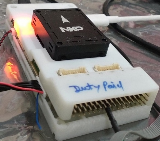
NXP FMURT6
Overview
The MIMXRT1062_FMURT6 adds to the industry’s crossover processor series and expands the i.MX RT series to three scalable families.
The i.MX RT1062 doubles the On-Chip SRAM to 1MB while keeping pin-to-pin compatibility with i.MX RT1050. This series introduces additional features ideal for real-time applications such as High-Speed GPIO, CAN FD, and synchronous parallel NAND/NOR/PSRAM controller. The i.MX RT1062 runs on the Arm® Cortex-M7® core up to 600 MHz.
Hardware
MIMXRT1062DVL6B MCU (600 MHz, 1024 KB on-chip memory)
Memory
256 Mbit SDRAM
512 Mbit Hyper Flash
TF socket for SD card
Ethernet
10/100 Mbit/s Ethernet PHY
USB
USB 2.0 OTG connector
USB 2.0 host connector
Audio
3.5 mm audio stereo headphone jack
Board-mounted microphone
Left and right speaker out connectors
Power
5 V DC jack
Debug
JTAG 20-pin connector
OpenSDA with DAPLink
Sensor
BMI088 6-axis e-compass
Expansion port
Arduino interface
CAN bus connector
For more information about the MIMXRT1062 SoC and MIMXRT1062-FMURT6 board, see these references:
Supported Features
The mimxrt1062_fmurt6 board configuration supports the hardware features listed below. For additional features not yet supported, please also refer to the NXP MIMXRT1064-EVK , which is the superset board in NXP’s i.MX RT10xx family. NXP prioritizes enabling the superset board with NXP’s Full Platform Support for Zephyr. Therefore, the mimxrt1064_evk board may have additional features already supported, which can also be re-used on this mimxrt1060_evk board:
Interface |
Controller |
Driver/Component |
|---|---|---|
NVIC |
on-chip |
nested vector interrupt controller |
SYSTICK |
on-chip |
systick |
DISPLAY |
on-chip |
display |
FLASH |
on-chip |
QSPI hyper flash |
GPIO |
on-chip |
gpio |
SPI |
on-chip |
spi |
I2C |
on-chip |
i2c |
ADC |
on-chip |
adc |
WATCHDOG |
on-chip |
watchdog |
PWM |
on-chip |
pwm |
UART |
on-chip |
serial port-polling; serial port-interrupt |
ENET |
on-chip |
ethernet |
USB |
on-chip |
USB device |
CAN |
on-chip |
can |
DMA |
on-chip |
dma |
GPT |
on-chip |
gpt |
FLEXSPI |
on-chip |
flash programming |
The default configuration can be found in the defconfig file:
boards/arm/mimxrt1062_fmurt6/mimxrt1062_fmurt6_defconfig
Other hardware features are not currently supported by the port.
Connections and I/Os
The MIMXRT1062 SoC has five pairs of pinmux/gpio controllers.
Name |
Function |
Usage |
|---|---|---|
GPIO_AD_B1_08 |
FLEXCAN1 TX |
CAN |
GPIO_B0_03 |
FLEXCAN1 RX |
CAN |
GPIO_AD_B0_06 |
PWM2A0 |
PWM |
GPIO_EMC_08 |
PWM2A1 |
PWM |
GPIO_EMC_10 |
PWM2A2 |
PWM |
GPIO_AD_B0_09 |
PWM2A3 |
PWM |
GPIO_EMC_31 |
LPUART7_TX |
UART Console |
GPIO_EMC_32 |
LPUART7_RX |
UART Console |
GPIO_B0_04 |
LPI2C2_SCL |
I2C |
GPIO_B0_05 |
LPI2C2_SDA |
I2C |
GPIO_AD_B1_00 |
LPI2C1_SCL |
I2C |
GPIO_AD_B1_01 |
LPI2C1_SDA |
I2C |
GPIO_AD_B0_12 |
LPI2C4_SCL |
I2C |
GPIO_AD_B0_13 |
LPI2C4_SDA |
I2C |
WAKEUP |
GPIO |
SW0 |
GPIO_B1_01 |
ENET_RX_DATA00 |
Ethernet |
GPIO_B1_02 |
ENET_RX_DATA01 |
Ethernet |
GPIO_B1_03 |
ENET_RX_EN |
Ethernet |
GPIO_B0_12 |
ENET_TX_DATA00 |
Ethernet |
GPIO_B0_13 |
ENET_TX_DATA01 |
Ethernet |
GPIO_B0_14 |
ENET_TX_EN |
Ethernet |
GPIO_B0_15 |
ENET_REF_CLK |
Ethernet |
GPIO_B1_00 |
ENET_RX_ER |
Ethernet |
GPIO_B1_12 |
GPIO |
SD Card |
GPIO_B1_14 |
USDHC1_VSELECT |
SD Card |
GPIO_EMC_40 |
ENET_MDC |
Ethernet |
GPIO_B0_01 |
ENET_MDIO |
Ethernet |
GPIO_SD_B0_00 |
USDHC1_CMD |
SD Card |
GPIO_SD_B0_01 |
USDHC1_CLK |
SD Card |
GPIO_SD_B0_02 |
USDHC1_DATA0 |
SD Card |
GPIO_SD_B0_03 |
USDHC1_DATA1 |
SD Card |
GPIO_SD_B0_04 |
USDHC1_DATA2 |
SD Card |
GPIO_SD_B0_05 |
USDHC1_DATA3 |
SD Card |
GPIO_EMC_27 |
LPSPI1_SCK |
SPI |
GPIO_EMC_28 |
LPSPI1_SDO |
SPI |
GPIO_EMC_29 |
LPSPI1_SDI |
SPI |
GPIO_EMC_00 |
LPSPI2_SCK |
SPI |
GPIO_EMC_02 |
LPSPI2_SDO |
SPI |
GPIO_EMC_03 |
LPSPI2_SDI |
SPI |
GPIO_AD_B1_15 |
LPSPI3_SCK |
SPI |
GPIO_AD_B1_14 |
LPSPI3_SDO |
SPI |
GPIO_AD_B1_13 |
LPSPI3_SDI |
SPI |
GPIO_AD_B1_11 |
ADC |
ADC1 Channel 0 |
GPIO_AD_B1_09 |
ADC |
ADC1 Channel 14 |
GPIO_AD_B0_15 |
ADC |
ADC1 Channel 4 |
GPIO_AD_B1_02 |
UART2_TX_GPS1 |
UART GPS |
GPIO_AD_B1_03 |
UART2_RX_GPS1 |
UART GPS |
System Clock
The MIMXRT1062 SoC is configured to use SysTick as the system clock source, running at 600MHz.
When power management is enabled, the 32 KHz low frequency oscillator on the board will be used as a source for the GPT timer to generate a system clock. This clock enables lower power states, at the cost of reduced resolution
Serial Port
The MIMXRT1062 SoC has eight UARTs. LPUART7 is configured for the console,
LPUART8 and 2 for GPS/MAG, LPUART3 and 4 for Telemetry and the remaining are not used.
Programming and Debugging
Build and flash applications as usual (see Building an Application and Run an Application for more details).
Configuring a Debug Probe
A debug probe is used for both flashing and debugging the board. This board is configured by default to use the OpenSDA DAPLink Onboard Debug Probe, however the pyOCD Debug Host Tools do not yet support programming the external flashes on this board so you must reconfigure the board for one of the following debug probes instead.
Using J-Link
Install the J-Link Debug Host Tools and make sure they are in your search path.
For Hyperflash support on i.MxRT106x use JLink_V780 or above.
There are two options: the onboard debug circuit can be updated with Segger J-Link firmware, or J-Link External Debug Probe can be attached to the FMURT6 on J23 FMU Debug Port. Run JLink.exe and choose device / core as MIMXRT106A-ALEXA.
Configuring a Console
Regardless of your choice in debug probe, we will use the OpenSDA microcontroller as a usb-to-serial adapter for the serial console.
Connect a USB cable from your PC to PixHawk debug adapter.
Use the following settings with your serial terminal of choice (minicom, putty, etc.):
Speed: 115200
Data: 8 bits
Parity: None
Stop bits: 1
Using SWO
SWO can be used as a logging backend, by setting CONFIG_LOG_BACKEND_SWO=y.
Your SWO viewer should be configured with a CPU frequency of 132MHz, and
SWO frequency of 7500KHz.
Flashing
Here is an example for the Hello World application.
# From the root of the zephyr repository
west build -b mimxrt1062_fmurt6 samples/hello_world
west flash
Open a serial terminal, reset the board (press the SW9 button), and you should see the following message in the terminal:
***** Booting Zephyr OS v3.20.0 *****
Hello World! mimxrt1062_fmurt6
Debugging
Here is an example for the Hello World application.
# From the root of the zephyr repository
west build -b mimxrt1062_fmurt6 samples/hello_world
west debug
Open a serial terminal, step through the application in your debugger, and you should see the following message in the terminal:
***** Booting Zephyr OS v3.20.0 *****
Hello World! mimxrt1062_fmurt6
Troubleshooting
If the west flash or debug commands fail, and the command hangs while executing runners.jlink, confirm the J-Link debug probe is configured, powered, and connected to the FMURT6 properly.