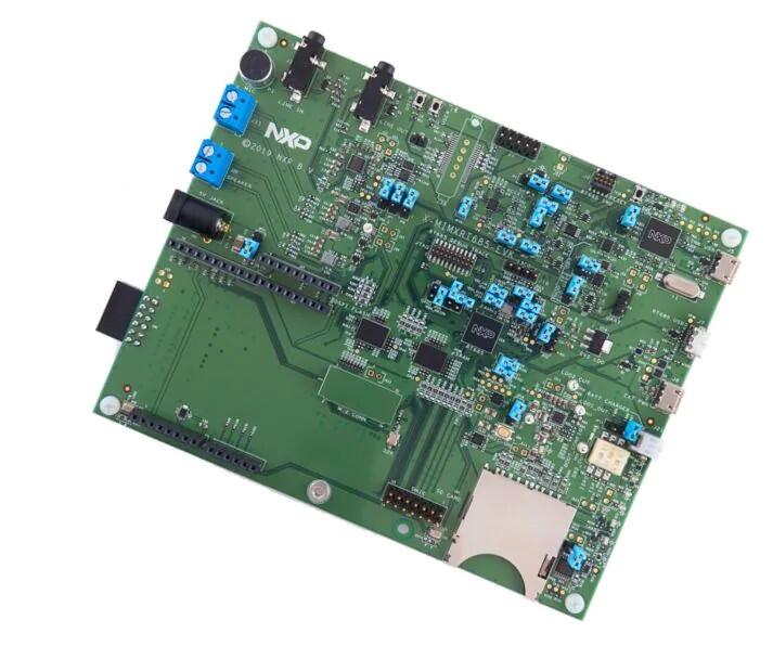
NXP MIMXRT685-EVK
Overview
The i.MX RT600 is a crossover MCU family optimized for 32-bit immersive audio playback and voice user interface applications combining a high-performance Cadence Tensilica HiFi 4 audio DSP core with a next-generation Cortex-M33 core. The i.MX RT600 family of crossover MCUs is designed to unlock the potential of voice-assisted end nodes with a secure, power-optimized embedded processor.
The i.MX RT600 family provides up to 4.5MB of on-chip SRAM and several high-bandwidth interfaces to access off-chip flash, including an Octal/Quad SPI interface with an on-the-fly decryption engine.
Hardware
MIMXRT685SFVKB Cortex-M33 (300 MHz, 128 KB TCM) core processor with Cadence Xtensa HiFi4 DSP
Onboard, high-speed USB, Link2 debug probe with CMSIS-DAP protocol (supporting Cortex M33 debug only)
High speed USB port with micro A/B connector for the host or device functionality
UART, I2C and SPI port bridging from i.MX RT685 target to USB via the on-board debug probe
512 MB Macronix Octal SPI Flash operating at 1.8 V
4.5 MB Apmemory PSRAM
Full size SD card slot (SDIO)
NXP PCA9420UK PMIC
User LEDs
Reset and User buttons
Arduino and PMod/Host expansion connectors
NXP FXOS8700CQ accelerometer
Stereo audio codec with line in/out and electret microphone
Stereo NXP TFA9894 digital amplifiers, with option for external +5V power for higher performance speakers
Support for up to eight off-board digital microphones via 12-pin header
Two on-board DMICS
For more information about the MIMXRT685 SoC and MIMXRT685-EVK board, see these references:
Supported Features
NXP considers the MIMXRT685-EVK as a superset board for the i.MX RT6xx family of MCUs. This board is a focus for NXP’s Full Platform Support for Zephyr, to better enable the entire RT6xx family. NXP prioritizes enabling this board with new support for Zephyr features. The mimxrt685_evk board configuration supports the hardware features below. Another very similar board is the NXP MIMXRT595-EVK, and that board may have additional features already supported, which can also be re-used on this mimxrt685_evk board:
Interface |
Controller |
Driver/Component |
|---|---|---|
NVIC |
on-chip |
nested vector interrupt controller |
SYSTICK |
on-chip |
systick |
OS_TIMER |
on-chip |
os timer |
IOCON |
on-chip |
pinmux |
GPIO |
on-chip |
gpio |
FLASH |
on-chip |
OctalSPI Flash |
USART |
on-chip |
serial port-polling; serial port-interrupt |
I2C |
on-chip |
i2c |
SPI |
on-chip |
spi |
I2S |
on-chip |
i2s |
CLOCK |
on-chip |
clock_control |
HWINFO |
on-chip |
Unique device serial number |
RTC |
on-chip |
counter |
PWM |
on-chip |
pwm |
WDT |
on-chip |
watchdog |
SDHC |
on-chip |
disk access |
USB |
on-chip |
USB device |
ADC |
on-chip |
adc |
CTIMER |
on-chip |
counter |
TRNG |
on-chip |
entropy |
FLEXSPI |
on-chip |
flash programming |
The default configuration can be found in the defconfig file:
boards/arm/mimxrt685_evk/mimxrt685_evk_cm33_defconfig
Other hardware features are not currently supported by the port.
Connections and IOs
The MIMXRT685 SoC has IOCON registers, which can be used to configure the functionality of a pin.
Name |
Function |
Usage |
|---|---|---|
PIO0_2 |
USART |
USART RX |
PIO0_1 |
USART |
USART TX |
PIO0_14 |
GPIO |
GREEN LED |
PIO1_1 |
GPIO |
SW0 |
PIO0_17 |
I2C |
I2C SDA |
PIO0_18 |
I2C |
I2C SCL |
PIO1_5 |
GPIO |
FXOS8700 TRIGGER |
PIO1_5 |
SPI |
SPI MOSI |
PIO1_4 |
SPI |
SPI MISO |
PIO1_3 |
SPI |
SPI SCK |
PIO1_6 |
SPI |
SPI SSEL |
PIO0_23 |
I2S |
I2S DATAOUT |
PIO0_22 |
I2S |
I2S TX WS |
PIO0_21 |
I2S |
I2S TX SCK |
PIO0_9 |
I2S |
I2S DATAIN |
PIO0_29 |
USART |
USART TX |
PIO0_30 |
USART |
USART RX |
PIO1_11 |
FLEXSPI0B_DATA0 |
OctalSPI Flash |
PIO1_12 |
FLEXSPI0B_DATA1 |
OctalSPI Flash |
PIO1_13 |
FLEXSPI0B_DATA2 |
OctalSPI Flash |
PIO1_14 |
FLEXSPI0B_DATA3 |
OctalSPI Flash |
PIO1_29 |
FLEXSPI0B_SCLK |
OctalSPI Flash |
PIO2_12 |
PIO2_12 |
OctalSPI Flash |
PIO2_17 |
FLEXSPI0B_DATA4 |
OctalSPI Flash |
PIO2_18 |
FLEXSPI0B_DATA5 |
OctalSPI Flash |
PIO2_19 |
FLEXSPI0B_SS0_N |
OctalSPI Flash |
PIO2_22 |
FLEXSPI0B_DATA6 |
OctalSPI Flash |
PIO2_23 |
FLEXSPI0B_DATA7 |
OctalSPI Flash |
PIO0_27 |
SCT0_OUT7 |
PWM |
PIO1_30 |
SD0_CLK |
SD card |
PIO1_31 |
SD0_CMD |
SD card |
PIO2_0 |
SD0_D0 |
SD card |
PIO2_1 |
SD0_D1 |
SD card |
PIO2_2 |
SD0_D2 |
SD card |
PIO2_3 |
SD0_D3 |
SD card |
PIO2_4 |
SD0_WR_PRT |
SD card |
PIO2_9 |
SD0_CD |
SD card |
PIO2_10 |
SD0_RST |
SD card |
System Clock
The MIMXRT685 EVK is configured to use the OS Event timer as a source for the system clock.
Serial Port
The MIMXRT685 SoC has 8 FLEXCOMM interfaces for serial communication. One is configured as USART for the console and the remaining are not used.
Programming and Debugging
Build and flash applications as usual (see Building an Application and Run an Application for more details).
Configuring a Debug Probe
A debug probe is used for both flashing and debugging the board. This board is configured by default to use the LPC-Link2.
Install the LinkServer Debug Host Tools and make sure they are in your search path. LinkServer works with the default CMSIS-DAP firmware included in the on-board debugger.
Make sure the jumpers JP17, JP18 and JP19 are installed.
linkserver is the default runner for this board
west flash
west debug
Install the J-Link Debug Host Tools and make sure they are in your search path.
To connect the SWD signals to onboard debug circuit, install jumpers JP17, JP18 and JP19, if not already done (these jumpers are installed by default).
Follow the instructions in LPC-Link2 J-Link Onboard Debug Probe to program the J-Link firmware. Please make sure you have the latest firmware for this board.
west flash -r jlink
west debug -r jlink
Install the J-Link Debug Host Tools and make sure they are in your search path.
To disconnect the SWD signals from onboard debug circuit, remove jumpers J17, J18, and J19 (these are installed by default).
Connect the J-Link probe to J2 10-pin header.
See J-Link External Debug Probe for more information.
west flash -r jlink
west debug -r jlink
Configuring a Console
Connect a USB cable from your PC to J16, and use the serial terminal of your choice (minicom, putty, etc.) with the following settings:
Speed: 115200
Data: 8 bits
Parity: None
Stop bits: 1
Flashing
Here is an example for the Hello World application. This example uses the LinkServer Debug Host Tools as default.
# From the root of the zephyr repository
west build -b mimxrt685_evk_cm33 samples/hello_world
west flash
Open a serial terminal, reset the board (press the RESET button), and you should see the following message in the terminal:
***** Booting Zephyr OS v1.14.0 *****
Hello World! mimxrt685_evk_cm33
Debugging
Here is an example for the Hello World application. This example uses the LinkServer Debug Host Tools as default.
# From the root of the zephyr repository
west build -b mimxrt685_evk_cm33 samples/hello_world
west debug
Open a serial terminal, step through the application in your debugger, and you should see the following message in the terminal:
***** Booting Zephyr OS zephyr-v2.3.0 *****
Hello World! mimxrt685_evk_cm33
Troubleshooting
If the debug probe fails to connect with the following error, it’s possible that the image in flash is interfering and causing this issue.
Remote debugging using :2331
Remote communication error.  Target disconnected.: Connection reset by peer.
"monitor" command not supported by this target.
"monitor" command not supported by this target.
You can't do that when your target is `exec'
(gdb) Could not connect to target.
Please check power, connection and settings.
You can fix it by erasing and reprogramming the flash with the following steps:
Set the SW5 DIP switches to ON-ON-ON to prevent booting from flash.
Reset by pressing SW3
Run
west debugorwest flashagain with a known working Zephyr application (example “Hello World”).Set the SW5 DIP switches to ON-OFF-ON to boot from flash.
Reset by pressing SW3