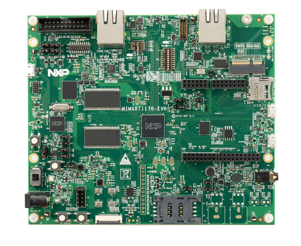
NXP MIMXRT1170-EVK/EVKB
Overview
The dual core i.MX RT1170 runs on the Cortex-M7 core at 1 GHz and on the Cortex-M4 at 400 MHz. The i.MX RT1170 MCU offers support over a wide temperature range and is qualified for consumer, industrial and automotive markets. Zephyr supports the initial revision of this EVK, as well as rev EVKB.
Hardware
MIMXRT1176DVMAA MCU
1GHz Cortex-M7 & 400Mhz Cortex-M4
2MB SRAM with 512KB of TCM for Cortex-M7 and 256KB of TCM for Cortex-M4
Memory
512 Mbit SDRAM
128 Mbit QSPI Flash
512 Mbit Octal Flash
2 Gbit raw NAND flash
64 Mbit LPSPI flash
TF socket for SD card
Display
MIPI LCD connector
Ethernet
10/100 Mbit/s Ethernet PHY
10/100/1000 Mbit/s Ethernet PHY
USB
USB 2.0 OTG connector
USB 2.0 host connector
Audio
3.5 mm audio stereo headphone jack
Board-mounted microphone
Left and right speaker out connectors
Power
5 V DC jack
Debug
JTAG 20-pin connector
on-board debugger
Sensor
FXOS8700CQ 6-axis e-compass
MIPI camera sensor connector
Expansion port
Arduino interface
CAN bus connector
For more information about the MIMXRT1170 SoC and MIMXRT1170-EVK board, see these references:
External Memory
This platform has the following external memories:
Device |
Controller |
Status |
|---|---|---|
W9825G6KH SDRAM |
SEMC |
Enabled via device configuration data (DCD) block, which sets up the SEMC at boot time |
IS25WP128 QSPI flash (RT1170 EVK) |
FLEXSPI |
Enabled via flash configuration block (FCB), which sets up the FLEXSPI at boot time. |
W25Q512NWEIQ QSPI flash (RT1170 EVKB) |
FLEXSPI |
Enabled via flash configuration block (FCB), which sets up the FLEXSPI at boot time. Supported for XIP only. |
Supported Features
NXP considers the MIMXRT1170-EVK as the superset board for the i.MX RT11xx family of MCUs. This board is a focus for NXP’s Full Platform Support for Zephyr, to better enable the entire RT11xx family. NXP prioritizes enabling this board with new support for Zephyr features. Note that this table covers two boards: the RT1170 EVK (mimxrt1170_evk_cm7/cm4), and RT1170 EVKB (mimxrt1170_evkb_cm7/cm4)
Interface |
Controller |
Driver/Component |
RT1170 EVK |
RT1170 EVKB |
|---|---|---|---|---|
NVIC |
on-chip |
nested vector interrupt controller |
Supported |
Supported |
SYSTICK |
on-chip |
systick |
Supported |
Supported |
GPIO |
on-chip |
gpio |
Supported |
Supported |
COUNTER |
on-chip |
gpt |
Supported |
Supported |
TIMER |
on-chip |
gpt |
Supported |
Supported |
CAN |
on-chip |
flexcan |
Supported (M7) |
Supported (M7) |
SPI |
on-chip |
spi |
Supported (M7) |
Supported |
I2C |
on-chip |
i2c |
Supported |
Supported |
PWM |
on-chip |
pwm |
Supported |
Supported |
ADC |
on-chip |
adc |
Supported (M7) |
Supported (M7) |
UART |
on-chip |
serial port-polling; serial port-interrupt; serial port-async |
Supported |
Supported |
DMA |
on-chip |
dma |
Supported |
Supported |
WATCHDOG |
on-chip |
watchdog |
Supported (M7) |
Supported (M7) |
ENET ENET1G |
on-chip |
ethernet - 10/100M (ENET_QOS or GigE not supported yet) |
Supported (M7) |
No support |
SAI |
on-chip |
i2s |
Supported |
No support |
USB |
on-chip |
USB Device |
Supported (M7) |
Supported (M7) |
HWINFO |
on-chip |
Unique device serial number |
Supported (M7) |
Supported (M7) |
DISPLAY |
on-chip |
eLCDIF; MIPI-DSI. Tested with RK055HDMIPI4M MIPI Display, RK055HDMIPI4MA0 MIPI Display, and G1120B0MIPI MIPI Display shields |
Supported (M7) |
Supported (M7) |
ACMP |
on-chip |
analog comparator |
Supported |
No support |
CAAM RNG |
on-chip |
entropy |
Supported (M7) |
No support |
FLEXSPI |
on-chip |
flash programming |
Supported (M7) |
No support |
SDHC |
on-chip |
SD host controller |
Supported (M7) |
Supported (M7) |
The default configuration can be found in the defconfig files:
boards/arm/mimxrt1170_evk/mimxrt1170_evk_cm7_defconfig
boards/arm/mimxrt1170_evk/mimxrt1170_evkb_cm7_defconfig
Connections and I/Os
The MIMXRT1170 SoC has six pairs of pinmux/gpio controllers.
Name |
Function |
Usage |
WAKEUP |
GPIO |
SW7 |
GPIO_AD_04 |
GPIO |
LED |
GPIO_AD_24 |
LPUART1_TX |
UART Console |
GPIO_AD_25 |
LPUART1_RX |
UART Console |
GPIO_LPSR_00 |
CAN3_TX |
flexcan |
GPIO_LPSR_01 |
CAN3_RX |
flexcan |
GPIO_AD_29 |
SPI1_CS0 |
spi |
GPIO_AD_28 |
SPI1_CLK |
spi |
GPIO_AD_30 |
SPI1_SDO |
spi |
GPIO_AD_31 |
SPI1_SDI |
spi |
GPIO_AD_08 |
LPI2C1_SCL |
i2c |
GPIO_AD_09 |
LPI2C1_SDA |
i2c |
GPIO_LPSR_05 |
LPI2C5_SCL |
i2c |
GPIO_LPSR_04 |
LPI2C5_SDA |
i2c |
GPIO_AD_04 |
FLEXPWM1_PWM2 |
pwm |
GPIO_AD_32 |
ENET_MDC |
Ethernet |
GPIO_AD_33 |
ENET_MDIO |
Ethernet |
GPIO_DISP_B2_02 |
ENET_TX_DATA00 |
Ethernet |
GPIO_DISP_B2_03 |
ENET_TX_DATA01 |
Ethernet |
GPIO_DISP_B2_04 |
ENET_TX_EN |
Ethernet |
GPIO_DISP_B2_05 |
ENET_REF_CLK |
Ethernet |
GPIO_DISP_B2_06 |
ENET_RX_DATA00 |
Ethernet |
GPIO_DISP_B2_07 |
ENET_RX_DATA01 |
Ethernet |
GPIO_DISP_B2_08 |
ENET_RX_EN |
Ethernet |
GPIO_DISP_B2_09 |
ENET_RX_ER |
Ethernet |
GPIO_AD_17_SAI1_MCLK |
SAI_MCLK |
SAI |
GPIO_AD_21_SAI1_TX_DATA00 |
SAI1_TX_DATA |
SAI |
GPIO_AD_22_SAI1_TX_BCLK |
SAI1_TX_BCLK |
SAI |
GPIO_AD_23_SAI1_TX_SYNC |
SAI1_TX_SYNC |
SAI |
GPIO_AD_17_SAI1_MCLK |
SAI1_MCLK |
SAI |
GPIO_AD_20_SAI1_RX_DATA00 |
SAI1_RX_DATA00 |
SAI |
Dual Core samples
Core |
Boot Address |
Comment |
|---|---|---|
Cortex M7 |
0x30000000[630K] |
primary core |
Cortex M4 |
0x20020000[96k] |
boots from OCRAM |
Memory |
Address[Size] |
Comment |
|---|---|---|
flexspi1 |
0x30000000[16M] |
Cortex M7 flash |
sdram0 |
0x80030000[64M] |
Cortex M7 ram |
ocram |
0x20020000[512K] |
Cortex M4 “flash” |
sram1 |
0x20000000[128K] |
Cortex M4 ram |
ocram2 |
0x200C0000[512K] |
Mailbox/shared memory |
Only the first 16K of ocram2 has the correct MPU region attributes set to be used as shared memory
System Clock
The MIMXRT1170 SoC is configured to use SysTick as the system clock source, running at 996MHz. When targeting the M4 core, SysTick will also be used, running at 400MHz
When power management is enabled, the 32 KHz low frequency oscillator on the board will be used as a source for the GPT timer to generate a system clock. This clock enables lower power states, at the cost of reduced resolution
Serial Port
The MIMXRT1170 SoC has 12 UARTs. One is configured for the console and the remaining are not used.
Programming and Debugging
Build and flash applications as usual (see Building an Application and Run an Application for more details).
Building a Dual-Core Image
Dual core samples load the M4 core image from flash into the shared ocram
region. The M7 core then sets the M4 boot address to this region. The only
sample currently enabled for dual core builds is the openamp sample.
To flash a dual core sample, the M4 image must be flashed first, so that it is
written to flash. Then, the M7 image must be flashed. The openamp sysbuild
sample will do this automatically by setting the image order.
The secondary core can be debugged normally in single core builds
(where the target is mimxrt1170_evk_cm4). For dual core builds, the
secondary core should be placed into a loop, then a debugger can be attached
(see AN13264, section 4.2.3 for more information)
Configuring a Debug Probe
A debug probe is used for both flashing and debugging the board. The on-board debugger listed below works with the LinkServer runner by default, or can be reprogrammed with JLink firmware. - MIMXRT1170-EVKB: MCU-Link CMSIS-DAP Onboard Debug Probe - MIMXRT1170-EVK: OpenSDA DAPLink Onboard Debug Probe
Using J-Link
JLink is the default runner for this board. Install the J-Link Debug Host Tools and make sure they are in your search path.
There are two options: the onboard debug circuit can be updated with Segger J-Link firmware, or J-Link External Debug Probe can be attached to the EVK. See Using J-Link with MIMXRT1170-EVKB or Using J-Link with MIMXRT1160-EVK or MIMXRT1170-EVK for more details.
Using LinkServer
Known limitations with LinkServer and these boards include:
- west debug does not yet work correctly, and the application image is not
properly written to the memory. NXP MCUXpresso for Visual Studio Code
can be used to debug Zephyr applications with LinkServer.
- west flash will not write images to non-flash locations. The flash
command only works when all data in the image is written to flash memory
regions.
Install the LinkServer Debug Host Tools and make sure they are in your search path. LinkServer works with the default CMSIS-DAP firmware included in the on-board debugger.
Use the -r linkserver option with West to use the LinkServer runner.
west flash -r linkserver
Alternatively, pyOCD can be used to flash and debug the board by using the
-r pyocd option with West. pyOCD is installed when you complete the
Get Zephyr and install Python dependencies step in the Getting Started Guide. The runners supported
by NXP are LinkServer and JLink. pyOCD is another potential option, but NXP
does not test or support the pyOCD runner.
Configuring a Console
We will use the on-board debugger microcontroller as a usb-to-serial adapter for the serial console. The following jumper settings are default on these boards, and are required to connect the UART signals to the USB bridge circuit: - MIMXRT1170-EVKB: JP2 open (default) - MIMXRT1170-EVK: J31 and J32 shorted (default)
Connect a USB cable from your PC to the on-board debugger USB port: - MIMXRT1170-EVKB: J86 - MIMXRT1170-EVK: J11
Use the following settings with your serial terminal of choice (minicom, putty, etc.):
Speed: 115200
Data: 8 bits
Parity: None
Stop bits: 1
Flashing
Here is an example for the Hello World application.
Before powering the board, make sure SW1 is set to 0001b
# From the root of the zephyr repository
west build -b mimxrt1170_evk_cm7 samples/hello_world
west flash
Power off the board, and change SW1 to 0010b. Then power on the board and open a serial terminal, reset the board (press the SW4 button), and you should see the following message in the terminal:
***** Booting Zephyr OS v3.4.0-xxxx-xxxxxxxxxxxxx *****
Hello World! mimxrt1170_evk_cm7
Debugging
Here is an example for the Hello World application.
# From the root of the zephyr repository
west build -b mimxrt1170_evk_cm7 samples/hello_world
west debug
Open a serial terminal, step through the application in your debugger, and you should see the following message in the terminal:
***** Booting Zephyr OS v3.4.0-xxxx-xxxxxxxxxxxxx *****
Hello World! mimxrt1170_evk_cm7
Experimental ENET Driver
Current default ethernet driver is eth_mcux, with binding nxp,kinetis-ethernet. There is a new driver with binding nxp,enet, which is experimental and undergoing development, but will have enhanced capability, such as not hardcoding code for only one phy in the driver like eth_mcux.
To build for this EVK with the new driver, include the experimental overlay to west build with the option -DEXTRA_DTC_OVERLAY_FILE=nxp,enet-experimental.overlay.