Important: We're excited to introduce our new technical documentation platform docs.nordicsemi.com, currently in Beta version. We invite you to explore it and share your feedback. Read more on our DevZone blog.
Nordic Thingy:91 is a battery-operated prototyping platform for cellular IoT systems, designed especially for asset tracking applications and environmental monitoring.
Thingy:91 integrates an nRF9160 SiP that supports LTE-M, NB-IoT, and Global Navigation Satellite System (GNSS) and an nRF52840 SoC that supports Bluetooth® Low Energy, Near Field Communication (NFC) and USB.
You can find more information on the product in the Thingy:91 product page and in the Nordic Thingy:91 User Guide.
The nRF Connect SDK provides support for developing applications on the Thingy:91.
If you are not familiar with the nRF Connect SDK, see Installation and Configuration and building documentation to install the nRF Connect SDK and learn more about its development environment.
This guide gives you more information on the various aspects of Thingy:91.
By default, the Bluetooth LE interface is off, as the connection is not encrypted or authenticated.
To turn it on at runtime, set the appropriate option in the Config.txt file located on the USB Mass storage Device.
You can use the nRF Connect Serial Terminal application to get debug output and send AT commands to the Thingy:91.
In the case of nRF Connect Serial Terminal or Cellular Monitor, the baud rate for the communication is set automatically.
To connect to the Thingy:91 using the nRF Connect Serial Terminal app, complete the following steps:
Find Serial Terminal in the list of applications and click Install.
Connect the Thingy:91 to a computer with a micro-Universal Serial Bus (USB) cable.
Make sure that the Thingy:91 is powered on.
Launch the Serial Terminal application.
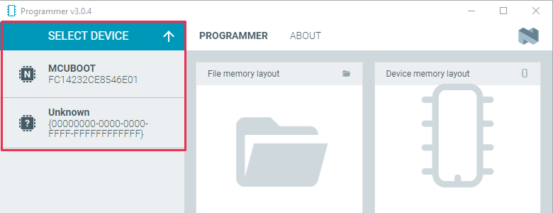
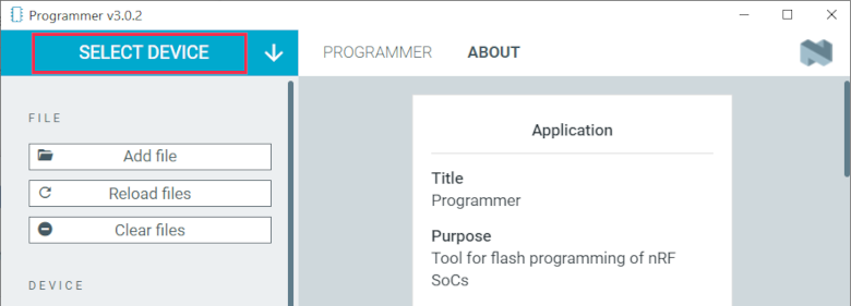
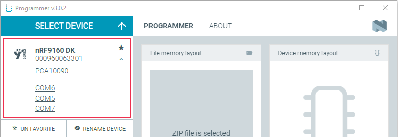
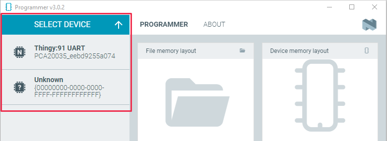
In the navigation bar, click SELECT DEVICE.
A drop-down menu appears.
In the menu, select Thingy:91.
In the terminal window, send an AT command to the modem.
If the connection is working, the modem responds with OK.
The terminal view shows all of the Asset Tracker v2 debug output as well as the AT commands and their results.
For information on the available AT commands, see the nRF9160 AT Commands Reference Guide.
Thingy:91 contains RGB indicator LEDs, which indicate the operating state of the device as described in the LED indication section of the User Interface module.
Thingy:91 has a GNSS receiver, which, if activated, allows the device to be located globally using GNSS signals.
In Asset Tracker v2, GNSS is activated by default.
The modem within Thingy:91 can be configured to use specific LTE bands by using the band lock AT command.
See Band lock and the band lock section in the nRF9160 AT Commands Reference Guide for additional information.
The preprogrammed firmware configures the modem to use the bands currently certified on the Thingy:91 hardware.
When building the firmware, you can configure which bands must be enabled.
Thingy:91 has a multimode modem, which enables it to support automatic switching between LTE-M and NB-IoT.
A built-in parameter in the Thingy:91 firmware determines whether the modem first attempts to connect in LTE-M or NB-IoT mode.
If the modem fails to connect using this preferred mode within the default timeout period (10 minutes), the modem switches to the other mode.
These operations can be done through USB using MCUboot, or through an external debug probe.
When developing with your Thingy:91, it is recommended to use an external debug probe.
Note
The external debug probe must support Arm Cortex-M33, such as the nRF9160 DK.
You need a 10-pin 2x5 socket-socket 1.27 mm IDC (Serial Wire Debug (SWD)) JTAG cable to connect to the external debug probe.
Download and extract the latest application and modem firmware from the Thingy:91 Downloads page.
The downloaded ZIP archive contains the following firmware:
Application firmware
The img_app_bl folder contains full firmware images for different applications.
The guides for programming through an external debug probe in this section use the images in this folder.
Application firmware for Device Firmware Update (DFU)
The images in the img_fota_dfu_bin and img_fota_dfu_hex folders contain firmware images for DFU.
The guides for programming through USB in this section use the images in the img_fota_dfu_hex folder.
Modem firmware
The modem firmware is in a ZIP archive instead of a folder.
The archive is named mfw_nrf9160_ followed by the firmware version number.
Do not unzip this file.
The CONTENTS.txt file in the extracted folder contains the location and names of the different firmware images.
The instructions in this section show you how to program the Connectivity bridge and Asset Tracker v2 applications, as well as the modem firmware.
Connectivity bridge provides bridge functionality for the hardware, and Asset Tracker v2 simulates sensor data and transmits it to Nordic Semiconductor’s cloud solution, nRF Cloud.
The data is transmitted using either LTE-M or NB-IoT.
Asset Tracker v2 first attempts to use LTE-M, then NB-IoT.
Check with your SIM card provider for the mode they support at your location.
For the iBasis SIM card provided with the Thingy:91, see iBasis IoT network coverage.
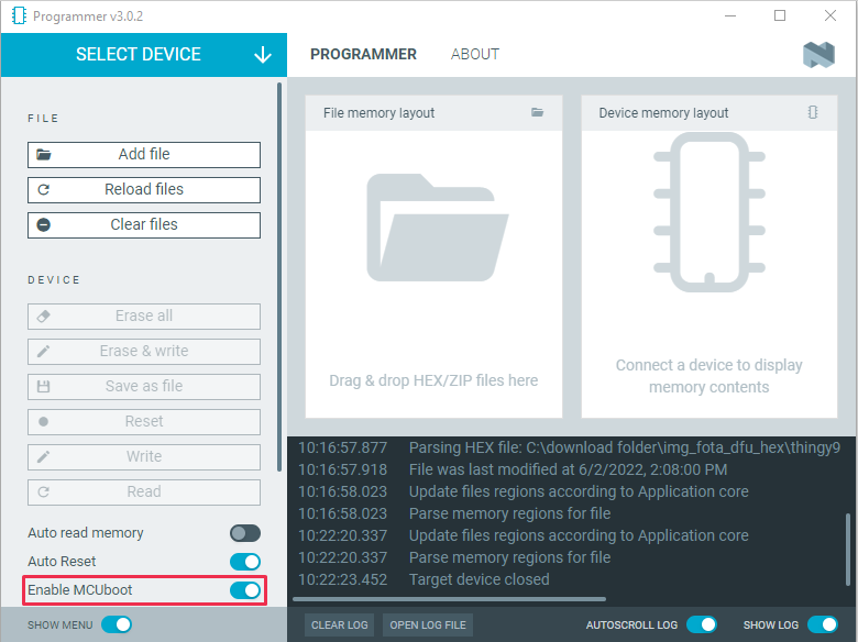
To update the Thingy:91 through USB, the nRF9160 SiP and nRF52840 SoC bootloaders must be factory-compatible.
The bootloaders might not be factory-compatible if the nRF9160 SiP or nRF52840 SoC has been updated with an external debug probe.
To restore the bootloaders, program the nRF9160 SiP or nRF52840 SoC with factory-compatible Thingy:91 firmware files through an external debug probe.
Note
You can also use these precompiled firmware image files for restoring the firmware to its initial image.
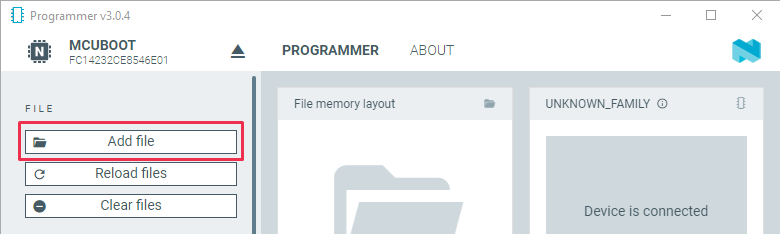
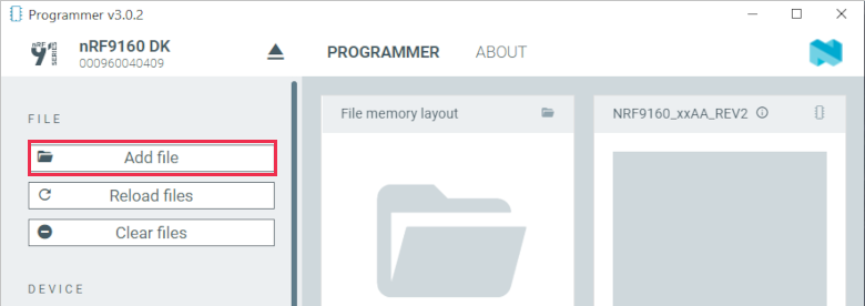
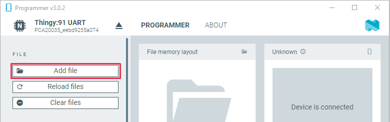
Open the folder img_app_bl that contains the HEX files for flashing with a debugger.
See the CONTENTS.txt file for information on which file you need.
Select the Connectivity bridge firmware file.
Click Open.
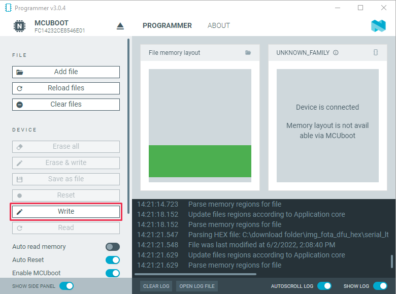
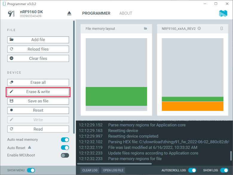
Scroll down in the menu on the left to the DEVICE section and click Erase & write.
The update is completed when the animation in Programmer’s Device memory layout window ends.
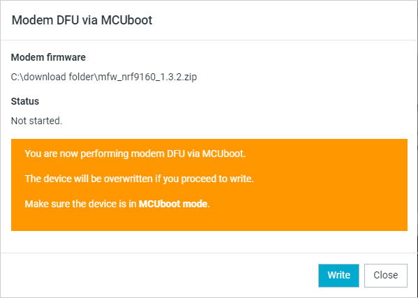
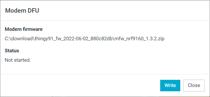
In the Modem DFU window, click Write.
When the update is complete, a “Completed successfully” message appears.
Note
Before trying to update the modem again, click the Erase all button. In this case, the contents of the flash memory are deleted and the applications must be reprogrammed.
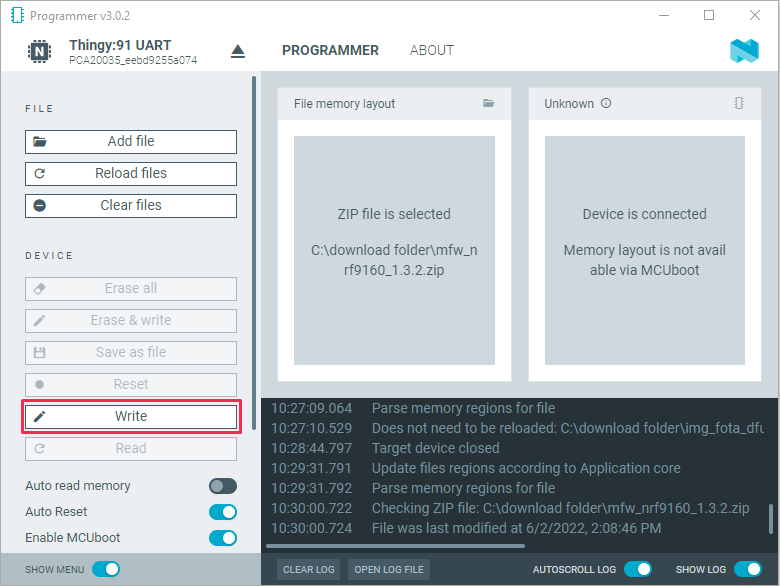
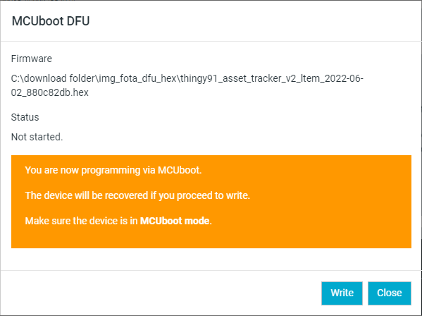
Open the folder img_fota_dfu_hex that contains the HEX files for updating over USB.
See the CONTENTS.txt file for information on which file you need.
Select the appropriate Asset Tracker v2 firmware file.
Note
If you are connecting over NB-IoT and your operator does not support extended Protocol Configuration Options (ePCO), select the file that has legacy Protocol Configuration Options (PCO) mode enabled.
Click Open.
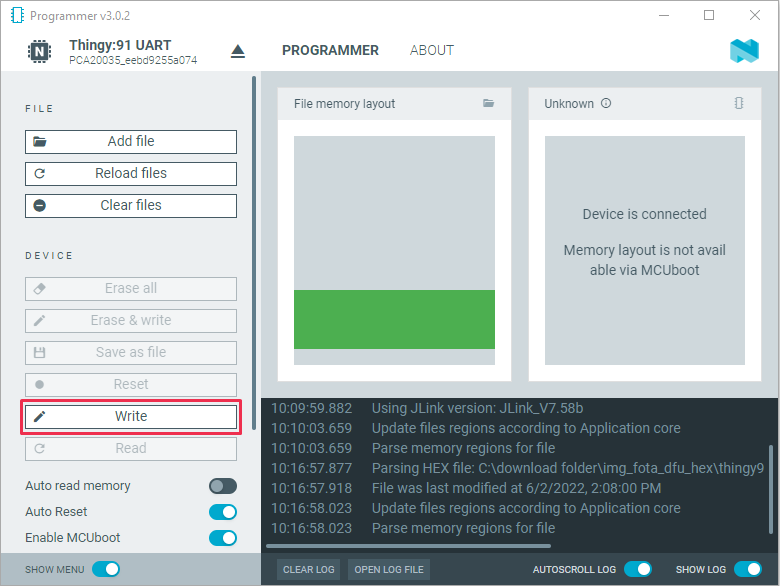
Scroll down in the menu on the left to the DEVICE section and click Write.
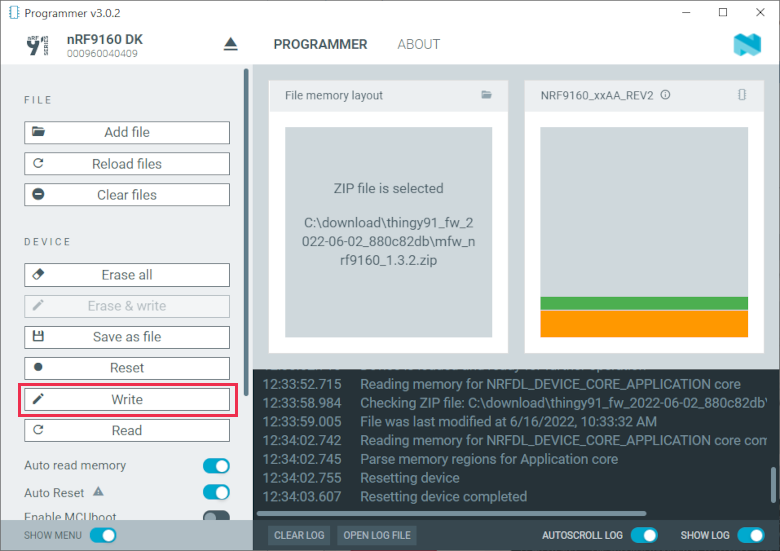
Open the folder img_app_bl that contains the HEX files for updating using a debugger.
See the CONTENTS.txt file for information on which file you need.
Select the appropriate Asset Tracker v2 firmware file.
Note
If you are connecting over NB-IoT and your operator does not support extended Protocol Configuration Options (ePCO), select the file that has legacy Protocol Configuration Options (PCO) mode enabled.
Click Open.
Scroll down in the menu on the left to the DEVICE section and click Erase & write.
The update is completed when the animation in Programmer’s Device memory layout window ends.
You can also program the Thingy:91 by using the images obtained by building the code in an nRF Connect SDK environment.
To set up your system to be able to build a compatible firmware image, follow the Installation guide for the nRF Connect SDK and read the Configuration and building documentation.
The build targets of interest for Thingy:91 in nRF Connect SDK are as follows:
Component
Build target
nRF9160 SiP
thingy91_nrf9160_ns
nRF52840 SoC
thingy91_nrf52840
You must use the build target thingy91_nrf9160_ns when building the application code for the nRF9160 SiP and the build target thingy91_nrf52840 when building the application code for the onboard nRF52840 SoC.
Note
In nRF Connect SDK releases before v1.3.0, these build targets were named nrf9160_pca20035, nrf9160_pca20035ns, and nrf52840_pca20035.
In nRF Connect SDK releases ranging from v1.3.0 to v1.6.1, the build target thingy91_nrf9160_ns was named thingy91_nrf9160ns.
There are multiple methods of programming a sample or application onto a Thingy:91.
It is recommended to use an external debug probe to program the Thingy:91.
While building applications for Thingy:91, the build system changes the signing algorithm of MCUboot so that it uses the default RSA Keys.
This is to ensure backward compatibility with the MCUboot versions that precede the nRF Connect SDK v1.4.0.
The default RSA keys must only be used for development.
In a final product, you must use your own, secret keys.
See Using development keys for more information.
Complete the command-line build setup before you start building nRF Connect SDK projects on the command line.
To build and program the source code from the command line, complete the following steps:
Open a terminal window.
Go to the specific sample or application directory.
For example, the folder path is ncs/nrf/applications/asset_tracker_v2 when building the source code for the Asset Tracker v2 application on the nRF9160 SiP component and ncs/nrf/applications/connectivity_bridge when building the source code for the Connectivity bridge application on the nRF52840 SoC component.
To get the rest of the dependencies, run the westupdate command as follows:
west update
To build the sample or application code, run the westbuild command as follows:
west build -b build_target
The parameter build_target must be thingy91_nrf9160_ns if building for the nRF9160 SiP component and thingy91_nrf52840 if building for the nRF52840 SoC component.
Note
The parameter destination_directory_name can be used to optionally specify the destination directory in the west command.
Unless a destination_directory_name is specified, the build files are automatically generated in build/zephyr/.
Program the application:
Set the Thingy:91 SWD selection switch (SW2) to nRF91 or nRF52 depending on whether you want to program the nRF9160 SiP or the nRF52840 SoC component.
Connect the Thingy:91 to the debug out port on a 10-pin external debug probe, for example, nRF9160 DK (Development Kit), using a 10-pin JTAG cable.
Note
If you are using nRF9160 DK as the debug probe, make sure that VDD_IO (SW11) is set to 1.8 V on the nRF9160 DK.
Connect the external debug probe to the PC using a USB cable.
Make sure that the Thingy:91 and the external debug probe are powered on.
Program the sample or application to the device using the following command:
west flash
The device resets and runs the programmed sample or application.
When building firmware on the Thingy:91 board, a static partition layout matching the factory layout is used.
This ensures that programming firmware through USB works.
In this case, the MCUboot bootloader will not be updated.
So, to maintain compatibility, it is important that the image partitions do not get moved.
When programming the Thingy:91 through an external debug probe, all partitions, including MCUboot, are programmed.
This enables the possibility of using an updated bootloader or defining an application-specific partition layout.
Configure the partition layout using one of the following configuration options:
CONFIG_THINGY91_STATIC_PARTITIONS_FACTORY - This option is the default Thingy:91 partition layout used in the factory firmware.
This ensures firmware updates are compatible with Thingy:91 when programming firmware through USB.
CONFIG_THINGY91_STATIC_PARTITIONS_SECURE_BOOT - This option is similar to the factory partition layout, but also has space for the immutable bootloader and two MCUboot slots.
A debugger is needed to program Thingy:91 for the first time.
This is an experimental feature.
CONFIG_THINGY91_NO_PREDEFINED_LAYOUT - Enabling this option disables Thingy:91 pre-defined static partitions.
This allows the application to use a dynamic layout or define a custom static partition layout for the application.
A debugger is needed to program Thingy:91 for the first time.
This is an experimental feature.