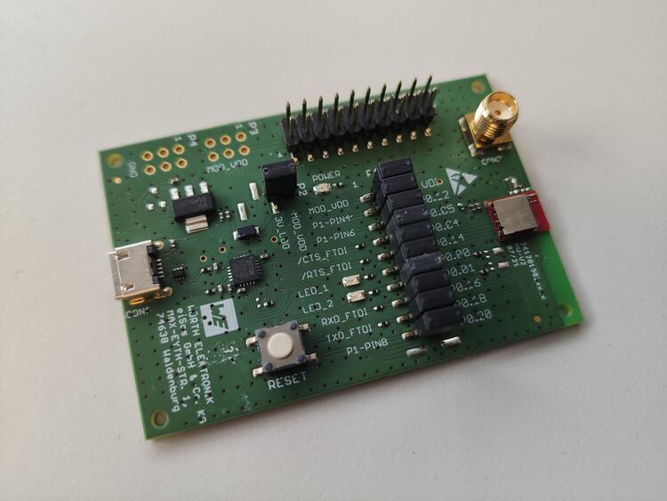
Ophelia-I EV NRF52805
Overview
The we_ophelia1ev_nrf52805 board is an evaluation board of the Ophelia-I radio module. It provides support for the Nordic Semiconductor nRF52805 ARM CPU and the following devices:
CLOCK
FLASH
GPIO
I2C
NVIC
RADIO (Bluetooth Low Energy)
RTC
Segger RTT (RTT Console)
SPI
UART
WDT

Fig. 200 Ophelia-I EV (Credit: Würth Elektronik)
Hardware
The Ophelia-I uses the internal low frequency RC oscillator and provides the so called smart antenna connection, that allows to choose between the module’s integrated PCB antenna and an external antenna that can be connected to the available SMA connector.
Supported Features
The we_ophelia1ev_nrf52805 board configuration supports the following hardware features:
Interface |
Controller |
Driver/Component |
|---|---|---|
CLOCK |
on-chip |
clock_control |
FLASH |
on-chip |
flash |
GPIO |
on-chip |
gpio |
I2C(M) |
on-chip |
i2c |
MPU |
on-chip |
arch/arm |
NVIC |
on-chip |
arch/arm |
RADIO |
on-chip |
Bluetooth |
RTC |
on-chip |
system clock |
RTT |
Segger |
console |
SPI(M/S) |
on-chip |
spi |
UART |
on-chip |
serial |
WDT |
on-chip |
watchdog |
Programming and Debugging
Flashing
Follow the instructions in the Nordic nRF5x Segger J-Link page to install and configure all the necessary software. Further information can be found in Flashing. Then build and flash applications as usual (see Building an Application and Run an Application for more details).
Here is an example for the Hello World application.
First, run your favorite terminal program to listen for output.
$ minicom -D <tty_device> -b 115200
Replace <tty_device> with the port where the board nRF52 DK
can be found. For example, under Linux, /dev/ttyACM0.
Then build and flash the application in the usual way.
# From the root of the zephyr repository
west build -b nrf52dk_nrf52832 samples/hello_world
west flash
Debugging
Refer to the Nordic nRF5x Segger J-Link page to learn about debugging Nordic boards with a Segger IC.
