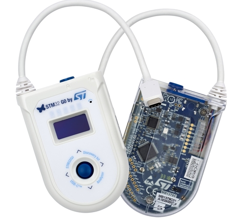
ST STM32G071B Discovery
Overview
The STM32G071B-DISCO Discovery board is a demonstration and development platform for the STMicroelectronics Arm® Cortex® -M0+ core-based STM32G071RB USB Type-C™ and Power Delivery microcontroller. The STM32G071B-DISCO Discovery board is presented with all necessary interfaces for easy connection and interoperability with other USB Type-C™ devices. The STM32G071B-DISCO Discovery board is intended for discovery and display of USB Type-C™ port characteristics such as data role, power role, VBUS and IBUS monitoring. It offers an advanced user mode when associated with the STM32CubeMonUCPD software GUI and can be used as a USB Type-C™ and Power Delivery analyzer.
STM32G071RBT6 microcontroller featuring 128 Kbytes of Flash memory and 32 Kbytes of RAM in LQFP64 package
Plastic case
1” 128 x 64 pixels OLED LCD module with SPI interface
USB Type-C™ interface plug cable and receptacle connector accessible by door with reed sensor detection
3 bidirectional current and power monitors with I2C interface to measure VBUS, CC1 and CC2 protected and isolated lines
On-board DC/DC converter to sustain power supply with VBUS varying from 3 V to 20 V (+/- 5 %)
4 user status LEDs about USB Type-C™ configuration
3 LEDs for power and ST-LINK communication
4-way joystick with selection button
1 reset push-button
- Board external connectors:
USB Type-C™ plug cable
USB Type-C™ receptacle connector
8-pin user extension connector including ADC, SPI, USART and I2C communication signals
USB with Micro-AB (ST-LINK)
- Board internal connectors:
- 2 x 8-pin GPIOs free pins from microcontroller
(accessible internally when case is removed)
USB Type-C™ test points for main signals
Flexible power-supply options: ST-LINK USB VBUS or USB Type-C™ VBUS
On-board ST-LINK/V2-1 debugger/programmer with USB enumeration capability: mass storage, Virtual COM port and debug port

More information about the board can be found at the STM32G071B-DISCO website 1.
More information about STM32G071RB can be found here: - G071RB on www.st.com 4 - STM32G071 reference manual 2
Supported Features
The Zephyr stm32g071b_disco board configuration supports the following hardware features:
Interface |
Controller |
Driver/Component |
|---|---|---|
NVIC |
on-chip |
nested vector interrupt controller |
UART |
on-chip |
serial port-polling; serial port-interrupt |
GPIO |
on-chip |
gpio |
WATCHDOG |
on-chip |
independent watchdog |
Other hardware features are not yet supported in this Zephyr port.
The default configuration can be found in the defconfig file:
boards/arm/stm32g071b_disco/stm32g071b_disco_defconfig
Connections and IOs
Each of the GPIO pins can be configured by software as output (push-pull or open-drain), as input (with or without pull-up or pull-down), or as peripheral alternate function. Most of the GPIO pins are shared with digital or analog alternate functions. All GPIOs are high current capable except for analog inputs.
Default Zephyr Peripheral Mapping:
UART_3 TX/RX : PC10/PC11 (ST-Link Virtual Port Com)
BUTTON (JOY_SEL) : PC0
BUTTON (JOY_LEFT) : PC1
BUTTON (JOY_DOWN) : PC2
BUTTON (JOY_RIGHT) : PC3
BUTTON (JOY_UP) : PC4
LED (TO_REC) : PD9
LED (TO_PLUG) : PD8
LED (SINK_SPY) : PD5
LED (SOURCE) : PC12
For mode details please refer to STM32G0 Discovery board User Manual 3.
Programming and Debugging
Applications for the stm32g071b_disco board configuration can be built and
flashed in the usual way (see Building an Application and
Run an Application for more details).
Flashing
The STM32G071B Discovery board includes an ST-LINK/V2-1 embedded debug tool interface.
$ west flash
Flashing an application to the STM32G071B_DISCO
Here is an example for the Blinky application.
# From the root of the zephyr repository
west build -b stm32g071b_disco samples/basic/blinky
west flash
You will see the LED blinking every second.
Debugging
You can debug an application in the usual way. Here is an example for the Hello World application.
# From the root of the zephyr repository
west build -b stm32g071b_disco samples/hello_world
west debug
