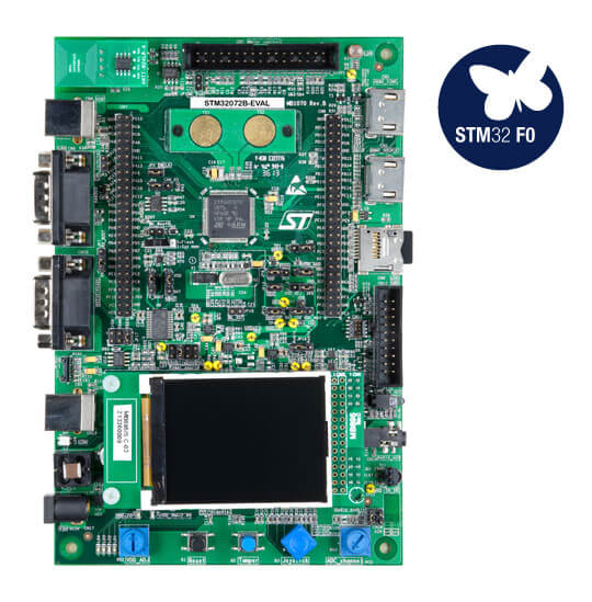
ST STM32F072 Evaluation
Overview
The STM32F072-EVAL Discovery kit features an ARM Cortex-M0 based STM32F072VBT6 MCU with a wide range of connectivity support and configurations. Here are some highlights of the STM32F072-EVAL board:
Four 5 V power supply options: power jack, ST-LINK/V2 USB connector, user USB connector, or daughter board
Stereo audio jack, which supports a headset with microphone connected to DAC and ADC of STM32F072VBT6.
2G Byte (or more) SPI interface MicroSD card
I2C compatible serial interface temperature sensor
RF E2PROM
RS232 and RS485 communication
IrDA transceiver
IR LED and IR receiver
SWD debug support, ST-LINK/V2 embedded
240x320 TFT color LCD connected to SPI interface of STM32F072VBT6
Joystick with 4-direction control and selector
Reset and tamper buttons
Four color user LEDs and two LEDs as MCU low power alarm
Extension connector for daughter board or wrapping board
MCU voltage choice: fixed 3.3 V or adjustable from 1.65 V to 3.6 V
USB full-speed connector
Touch sensing buttons
RTC with backup battery
CAN2.0A/B compliant connector
Light Dependent Resistor (LDR)
Potentiometer
Two HDMI connectors with DDC and CEC
Smart Card slot
Motor control connector

More information about the board can be found at the STM32F072-EVAL website.
Hardware
STM32F072-EVAL Discovery kit provides the following hardware components:
STM32F072VBT6 in LQFP100 package
ARM® 32-bit Cortex® -M0 CPU
48 MHz max CPU frequency
VDD from 2.0 V to 3.6 V
128 KB Flash
16 KB SRAM with HW parity
GPIO with external interrupt capability
one 12-bit ADC with 16 channels
one 12-bit D/A converters with 2 channels
RTC
Advanced-control Timer
General Purpose Timers (8)
Watchdog Timers (2)
USART (4)
I2C (2)
SPI (2)
CAN
USB 2.0 OTG FS with on-chip PHY
CRC calculation unit
DMA Controller
HDMI CEC Controller
24 capacitive sensing channels for touchkey, linear, and rotary touch sensors
Up to 87 fast I/Os: 68 I/Os with 5V tolerant capability and 19 with independent supply
- More information about STM32F072VB can be found here:
Supported Features
The Zephyr stm32f072_eval board configuration supports the following hardware features:
Interface |
Controller |
Driver/Component |
|---|---|---|
NVIC |
on-chip |
nested vector interrupt controller |
UART |
on-chip |
serial port-polling; serial port-interrupt |
PINMUX |
on-chip |
pinmux |
GPIO |
on-chip |
gpio |
PWM |
on-chip |
pwm |
CLOCK |
on-chip |
reset and clock control |
WATCHDOG |
on-chip |
independent watchdog |
Other hardware features are not yet supported on this Zephyr porting.
The default configuration can be found in the defconfig file:
boards/arm/stm32f072_eval/stm32f072_eval_defconfig
Pin Mapping
STM32F072-EVAL Discovery kit has 6 GPIO controllers. These controllers are responsible for pin muxing, input/output, pull-up, etc.
For mode details please refer to STM32F072-EVAL board User Manual.
Default Zephyr Peripheral Mapping:
UART_2_TX : PD5
UART_2_RX : PD6
TAMPER_PB : PC13
JOYSTICK_RIGHT_PB : PE3
JOYSTICK_LEFT_PB : PF2
JOYSTICK_UP_PB : PF9
JOYSTICK_DOWN_PB : PF10
JOYSTICK_SEL_PB : PA0
LD1 : PD8
LD2 : PD9
LD3 : PD10
LD4 : PD11
System Clock
STM32F072-EVAL System Clock could be driven by an internal or external oscillator, as well as the main PLL clock. By default the System clock is driven by the PLL clock at 48MHz, driven by an 8MHz high speed internal clock.
Serial Port
STM32F072-EVAL Discovery kit has up to 4 UARTs. The Zephyr console output is assigned to UART2. Default settings are 115200 8N1.
Programming and Debugging
Applications for the stm32f072_eval board configuration can be built and
flashed in the usual way (see Building an Application and
Run an Application for more details).
Flashing
STM32F072-EVAL Discovery kit includes an ST-LINK/V2 embedded debug tool interface. This interface is supported by the openocd version included in Zephyr SDK.
Flashing an application to STM32F072-EVAL
Here is an example for the Blinky application.
# From the root of the zephyr repository
west build -b stm32f072_eval samples/basic/blinky
west flash
You will see the LED blinking every second.
Debugging
You can debug an application in the usual way. Here is an example for the Blinky application.
# From the root of the zephyr repository
west build -b stm32f072_eval samples/basic/blinky
west debug
