Working with Thingy:91
Nordic Thingy:91 is a battery-operated prototyping platform for cellular IoT systems, designed especially for asset tracking applications and environmental monitoring.
Thingy:91 integrates the following components:
nRF9160 SiP - supporting LTE-M, NB-IoT, and Global Positioning System (GPS)
nRF52840 SoC - supporting Bluetooth Low Energy and Near Field Communication (NFC)
You can find more information on the product in the Thingy:91 product page and in the Nordic Thingy:91 User Guide. The nRF Connect SDK provides support for developing applications on the Thingy:91.
Connecting to Thingy:91 serial ports
For connecting to Thingy:91, you can use LTE Link Monitor, Trace Collector applications, or a serial terminal. In the case of LTE Link Monitor or Trace Collector applications, the baud rate for the communication is set automatically.
If you prefer to use a standard serial terminal, the baud rate has to be specified manually.
Thingy:91 uses the following UART baud rate configuration:
UART Interface |
Baud Rate |
|---|---|
UART_0 |
115200 |
UART_1 |
1000000 |
Firmware
The firmware of Thingy:91 has been developed using the nRF Connect SDK. It is open source, and can be modified according to specific needs. The nRF9160: Asset Tracker application firmware, which is preprogrammed in the Thingy:91, enables the device to use the environment sensors and provides an option of tracking the device using GPS.
The data, along with information about the device, is transmitted to Nordic Semiconductor’s cloud solution, nRF Cloud, where it can be visualized. See nRF9160: Asset Tracker for more information on the asset tracker application.
Operating modes
Thingy:91 contains RGB indicator LEDs, which indicate the operating state of the device as described in operating states of Thingy:91.
GPS
Thingy:91 has GPS, which, if activated, allows the device to be located globally using GPS signals. To activate GPS, long-press the SW3 button. See Button SW3 on Thingy:91 for information.
LTE Band Lock
The modem within Thingy:91 can be configured to use specific LTE bands by using the band lock AT command. See Band lock and the band lock section in the AT Commands reference document for additional information. The preprogrammed firmware configures the modem to use the bands currently certified on the Thingy:91 hardware. When building the firmware, you can configure which bands should be enabled.
LTE-M / NB-IoT switching
Thingy:91 has a multimode modem, which enables it to support automatic switching between LTE-M and NB-IoT. A built-in parameter in the Thingy:91 firmware determines whether the modem first attempts to connect in LTE-M or NB-IoT mode. If the modem fails to connect using this preferred mode within the default time-out period (10 minutes), the modem switches to the other mode.
Concurrent GPS and LTE
A Thingy:91 supports GPS in LTE-M and NB-IoT. Concurrent operation of GPS with optional power-saving features, such as extended Discontinuous Reception (eDRX) and Power Saving Mode (PSM), is also supported and recommended.
The following figure shows how the data transfer occurs in a Thingy:91 with power-saving in place.
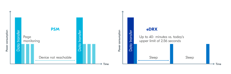
See Energy efficiency for more information.
Asset Tracker enables the concurrent working of GPS and LTE in eDRX and PSM modes when the device is in RRC idle mode. The time between the transition of a device from RRC connected mode (data transfer mode) to RRC idle mode is dependent on the network. Typically the time ranges between 5 seconds to 70 seconds after the last data transfer on LTE. Sensor and GPS data is sent to the cloud only during the data transfer phase.
Modem firmware
The functionality of the multimode modem of Thingy:91 is based on its firmware, which is available as a precompiled binary. You can download the modem firmware from the Thingy:91 product website (downloads). The downloadable zip file contains both the full firmware images that can be programmed using an external debug probe and the firmware images that can be used for updating the firmware through the built-in bootloader.
Programming precompiled firmware images
Precompiled firmware image files are useful in the following scenarios:
Restoring the firmware to its initial image
Updating the application firmware to a newly released version
Updating the modem firmware
Downloading precompiled firmware images
To obtain precompiled firmware images for updating the firmware, perform the following steps:
Go to the Thingy:91 product page and under the Downloads tab, navigate to Precompiled firmware.
Download and extract the latest Thingy:91 firmware package.
Check the
CONTENTS.txtfile in the extracted folder for the location and names of the different firmware images.
Quick programming of precompiled firmware images
When you have the precompiled firmware images ready, you can directly program the images onto the Thingy:91 using the nRF Connect Programmer app, which is available in nRF Connect for Desktop.
In this method, the Thingy:91 is connected directly to your PC through USB. This method makes use of the MCUboot feature and the inbuilt serial recovery mode of Thingy:91. You can program either the nRF9160 SiP or the nRF52840 SoC component on the Thingy:91.
Alternatively, you can use an external debug probe such as nRF9160 DK or any J-Link device supporting ARM Cortex-M33 to program applications on a Thingy:91.
See Programming applications on Nordic Thingy:91 for the detailed procedures to program a Thingy:91 using nRF Connect Programmer.
Updating the modem firmware
You can update the modem firmware of Thingy:91 using any of the following methods:
Using USB (MCUboot)
Using an external debug probe such as nRF9160 DK or any J-Link device supporting ARM Cortex-M33
See Programming the Thingy:91 modem for the detailed steps to update the modem firmware.
Building and programming from the source code
You can also program the Thingy:91 by using the images obtained by building the code in an nRF Connect SDK environment.
To set up your system to be able to build a compatible firmware image, follow the Getting started guide for nRF Connect SDK. The build targets of interest for Thingy:91 in nRF Connect SDK are as follows:
Component |
Build target |
|---|---|
nRF9160 SiP |
|
nRF52840 SoC |
|
You should use the build target thingy91_nrf9160 or thingy91_nrf9160ns when building the application code for the nRF9160 SiP and the build target thingy91_nrf52840 when building the application code for the onboard nRF52840 SoC.
Note
In nRF Connect SDK releases before v1.3.0, these build targets were named nrf9160_pca20035, nrf9160_pca20035ns, and nrf52840_pca20035.
Note
LTE/GPS features can only be used with non-secure target.
The table below shows the different types of build files that are generated and the different scenarios in which they are used:
File |
File format |
Programming scenario |
|---|---|---|
merged.hex |
Full image, HEX format |
Using an external debug probe and nRF Connect Programmer |
app_signed.hex |
MCUboot compatible image, HEX format |
Using the built-in bootloader and nRF Connect Programmer |
app_update.bin |
MCUboot compatible image, binary format |
|
There are multiple methods of programming a sample or application onto a Thingy:91. You can choose the method based on the availability or absence of an external debug probe to program.
Note
If you do not have an external debug probe available to program the Thingy:91, you can directly program by using the USB (MCUboot) method and nRF Connect Programmer.
In this scenario, use the app_signed.hex firmware image file.
Building and programming using SEGGER Embedded Studio
Complete the following steps to build nRF Connect SDK projects with SES after installing SEGGER Embedded Studio and completing the first time setup:
Start SEGGER Embedded Studio.
If you have installed the nRF Connect SDK using the Toolchain manager, click Open IDE next to the version you installed to start SES. If you have installed SES manually, run
bin/emStudio.Select File -> Open nRF Connect SDK Project.
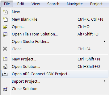
Open nRF Connect SDK Project menu
To import a project into SES, you must specify the following information:
nRF Connect SDK Release - Select the nRF Connect SDK version that you want to work with.
The drop-down list contains the current version of all nRF Connect SDK installation directories that SES knows about. To add a missing nRF Connect SDK installation directory to that list, run
west zephyr-exportin the installation repository or define the Zephyr base to point to the directory (see Setting up the SES environment).nRF Connect Toolchain Version - If you used the Toolchain manager to install the nRF Connect SDK, select the version of the toolchain that works with the selected nRF Connect SDK version. Otherwise, select NONE and make sure that your SES environment is configured correctly (see Setting up the SES environment).
Note
The drop-down list contains only toolchain versions that are compatible with the selected nRF Connect SDK version.
Projects - Select the project that you want to work with.
The drop-down list contains a selection of samples and applications from the sdk-nrf and sdk-zephyr repositories. Select any of the checkboxes underneath to add the samples from that area to the drop-down list. To add projects to the drop-down list, for example, your own custom projects, click … and select the folder that contains the projects that you want to add.
Board Name - Select the board that you want to work with.
The drop-down list contains the build targets for all Nordic Semiconductor boards that are defined in the sdk-nrf and sdk-zephyr repositories. Select any of the checkboxes underneath to add the build targets from that area to the drop-down list. To add build targets to the drop-down list, for example, targets for your own custom board, click … and select the folder that contains the board definitions.
Build Directory - Select the folder in which to run the build. The field is filled automatically based on the selected board name, but you can specify a different directory.
Clean Build Directory - Select this option to ensure that you are not building with an outdated build cache.
Extended Settings - Select this option to display a field where you can specify additional CMake options to be used for building. See Providing CMake options.
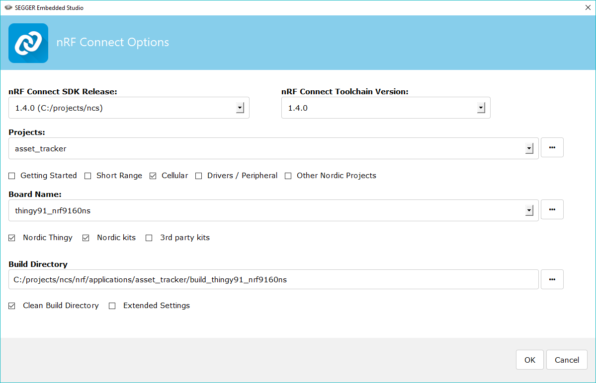
Opening the Asset tracker application for the thingy91_nrf9160ns build target
Note
The Board Directory folder can be found in the following location:
ncs/nrf/boards/arm.
Click OK to import the project into SES. You can now work with the project in the IDE.
Note
At this stage, you might get an error indicating a project load failure. For example:
Can't load project file
The project file <filepath> is invalid.
The reported error is 'solution load command failed (1)'
This issue might be caused by a variety of problems, such as incorrectly specified project file paths. SES helps you to identify the source of the issue by providing a text output with detailed information about the error. Make sure to click OK on the error pop-up message and then inspect the text output in SES.
To build the sample or application:
Select your project in the Project Explorer.
From the menu, select Build -> Build Solution. This builds the project.
You can find the output of the build, which includes the merged HEX file containing both the application and the SPM, in the
zephyrsubfolder in the build directory.
To program the sample or application:
Set the Thingy:91 SWD selection switch (SW2) to nRF91 or nRF52 depending on whether you want to program the nRF9160 SiP or the nRF52840 SoC component.
Connect the Thingy:91 to the debug out port on a 10-pin external debug probe, for example, nRF9160 DK (Development Kit), using a 10-pin JTAG cable.
Note
If you are using nRF9160 DK as the debug probe, make sure that VDD_IO (SW11) is set to 1.8 V on the nRF9160 DK.
Connect the external debug probe to the PC using a USB cable.
Make sure that the Thingy:91 and the external debug probe are powered on.
In SES, select Target -> Connect J-Link.
Select Target -> Download zephyr/merged.hex to program the sample or application onto Thingy:91.
The device will reset and run the programmed sample or application.
Building and programming on the command line
Complete the command-line build setup before you start building nRF Connect SDK projects on the command line.
To build and program the source code from the command line, complete the following steps:
Open a terminal window.
Go to the specific sample or application directory. For example, the folder path is
ncs/nrf/applications/asset_trackerwhen building the source code for the nRF9160: Asset Tracker application on the nRF9160 SiP component andncs/nrf/samples/usb/usb_uart_bridgewhen building the source code for the USB-UART bridge sample on the nRF52840 SoC component.Make sure that you have the required version of the nRF Connect SDK repository by pulling the nRF Connect SDK repository, sdk-nrf on GitHub using the procedures described in Obtaining a copy of the nRF Connect SDK and Updating a copy of the nRF Connect SDK.
To get the rest of the dependencies, run the
west updatecommand as follows:west update
To build the sample or application code, run the
west buildcommand as follows:west build -b board_name -d destination_directory_name
The parameter board_name should be
thingy91_nrf9160orthingy91_nrf9160nsif building for the nRF9160 SiP component andthingy91_nrf52840if building for the nRF52840 SoC component.Note
The parameter destination_directory_name can be used to optionally specify the destination directory in the west command. Unless a destination_directory_name is specified, the build files are automatically generated in
build/zephyr/.
To program the sample or application:
Set the Thingy:91 SWD selection switch (SW2) to nRF91 or nRF52 depending on whether you want to program the nRF9160 SiP or the nRF52840 SoC component.
Connect the Thingy:91 to the debug out port on a 10-pin external debug probe, for example, nRF9160 DK (Development Kit), using a 10-pin JTAG cable.
Note
If you are using nRF9160 DK as the debug probe, make sure that VDD_IO (SW11) is set to 1.8 V on the nRF9160 DK.
Connect the external debug probe to the PC using a USB cable.
Make sure that the Thingy:91 and the external debug probe are powered on.
Program the sample or application to the device using the following command:
west flashThe device will reset and run the programmed sample or application.