Testing a sample application
Follow the instructions in the testing section of the sample documentation to ensure that the application runs as expected.
Information about the current state of the application is usually provided through the LEDs or through UART, or through both. See the user interface section of the sample documentation for description of the LED states or available UART commands.
How to connect with PuTTY
To see the UART output, connect to the board with a terminal emulator, for example, PuTTY.
Connect with the following settings:
Baud rate: 115200
8 data bits
1 stop bit
No parity
HW flow control: None
If you want to send commands via UART, make sure to configure the required line endings and turn on local echo and local line editing:

UART can also be used for logging purposes as one of the logging backends.
How to use RTT
To view the logging output using Real Time Transfer (RTT), modify the configuration settings of the sample to override the default UART console:
CONFIG_USE_SEGGER_RTT=y
CONFIG_RTT_CONSOLE=y
CONFIG_UART_CONSOLE=n
SEGGER’s J-Link RTT can also be used for logging purposes as one of the logging backends.
Note
SEGGER’s J-Link RTT is part of the J-Link Software and Documentation Pack. You must have this software installed on your platform to use RTT.
Connecting via RTT
To run RTT on your platform, complete the following steps:
From the J-Link installation directory, open the J-Link RTT Viewer application:
On Windows, the executable is called
JLinkRTTViewer.exe.On Linux, the executable is called
JLinkRTTViewerExe.
Select the following options to configure your connection:
Connection to J-Link: USB
Target Device: Select your IC from the list
Target Interface and Speed: SWD, 4000 KHz
RTT Control Block: Auto Detection
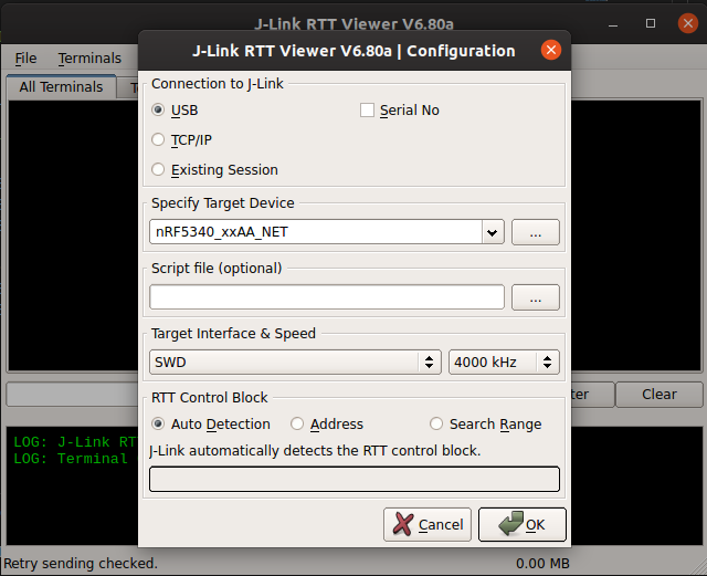
Click OK to view the logging output from the device.
How to connect with LTE Link Monitor
To connect to nRF9160-based boards (for example, the nRF9160 DK or Nordic Thingy:91), you can also use LTE Link Monitor, which is implemented in nRF Connect for Desktop. This application is used to establish LTE communication with the nRF9160 modem through AT commands, and it also displays the UART output.
To connect to the nRF9160-based board with LTE Link Monitor, perform the following steps:
Launch the LTE Link Monitor app.
Note
Make sure that Automatic requests is enabled in LTE Link Monitor.
Connect the nRF9160-based board to the PC with a USB cable.
Power on the nRF9160-based board.
Click Select Device and select the particular board entry from the drop-down list in the LTE Link Monitor.
Observe that the LTE Link monitor app starts AT communication with the modem of the nRF9160-based board and shows the status of the communication in the display terminal. The app also displays any information that is logged on UART.
Note
In the case of nRF9160 DK, the reset button must be pressed to restart the device and to start the application.