Pine64 PineTime DevKit0
Overview

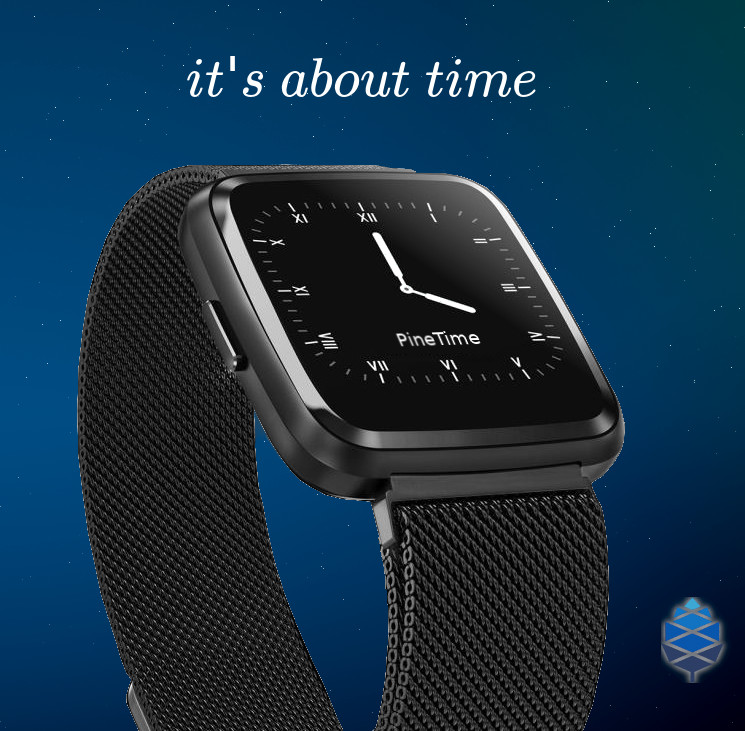
PineTime leaflet (Credit: Pine64)
The Pine64 smartwatch, dubbed “PineTime”, is a product of a community effort for an open source smartwatch in collaboration with wearable RTOS and Linux app developers/communities.

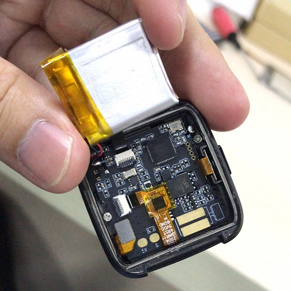
PineTime Dev Kit (Credit: Pine64)
Hardware
The PineTime is based on a Nordic NRF52832 chip and features:
64 MHz Cortex-M4 with FPU
64KB SRAM
512KB on board Flash
1.3 inches (33mm), 240x240 pixels display with ST7789 driver
170-180mAh LiPo battery
XT25F32B 32Mb (4MB) SPI NOR Flash
CST816S Capacitive Touch
BMA421 Triaxial Acceleration Sensor
HRS3300 PPG Heart Rate Sensor
PineTime Port Assignment
See PineTime schematics 1 +———————-+———————————+———–+ | NRF52 pins | Function | Direction | +======================+=================================+===========+ | P0.00/XL1 | 32.768 kHz –XL1 | | +———————-+———————————+———–+ | P0.01/XL2 | 32.768 kHz –XL2 | | +———————-+———————————+———–+ | P0.02/AIN0 | SPI-SCK, LCD_SCK | OUT | +———————-+———————————+———–+ | P0.03/AIN1 | SPI-MOSI, LCD_SDI | OUT | +———————-+———————————+———–+ | P0.04/AIN2 | SPI-MISO | IN | +———————-+———————————+———–+ | P0.05/AIN3 | SPI-CE# (SPI-NOR) | OUT | +———————-+———————————+———–+ | P0.06 | BMA421-SDA, HRS3300-SDA, TP-SDA | I/O | +———————-+———————————+———–+ | P0.07 | BMA421-SCL, HRS3300-SCL, TP-SCL | OUT | +———————-+———————————+———–+ | P0.08 | BMA421-INT | IN | +———————-+———————————+———–+ | P0.09/NFC1 | LCD_DET | OUT | +———————-+———————————+———–+ | P0.10/NFC2 | TP_RESET | OUT | +———————-+———————————+———–+ | P0.11 | | | +———————-+———————————+———–+ | P0.12 | CHARGE INDICATION | IN | +———————-+———————————+———–+ | P0.13 | PUSH BUTTON_IN | IN | +———————-+———————————+———–+ | P0.14/TRACEDATA3 | LCD_BACKLIGHT_LOW | OUT | +———————-+———————————+———–+ | P0.15/TRACEDATA2 | PUSH BUTTON_OUT | OUT | +———————-+———————————+———–+ | P0.16/TRACEDATA1 | VIBRATOR OUT | OUT | +———————-+———————————+———–+ | P0.17 | | | +———————-+———————————+———–+ | P0.18/TRACEDATA0/SWO | LCD_RS OUT | | +———————-+———————————+———–+ | P0.19 | POWER PRESENCE INDICATION | IN | +———————-+———————————+———–+ | P0.20/TRACECLK | | | +———————-+———————————+———–+ | P0.21/nRESET | | | +———————-+———————————+———–+ | P0.22 | LCD_BACKLIGHT_MID | OUT | +———————-+———————————+———–+ | P0.23 | LCD_BACKLIGHT_HIGH | OUT | +———————-+———————————+———–+ | P0.24 | 3V3 POWER CONTROL | OUT | +———————-+———————————+———–+ | P0.25 | LCD_CS | OUT | +———————-+———————————+———–+ | P0.26 | LCD_RESET | OUT | +———————-+———————————+———–+ | P0.27 | STATUS LED (NOT STAFF) | OUT | +———————-+———————————+———–+ | P0.28/AIN4 | TP_INT | IN | +———————-+———————————+———–+ | P0.29/AIN5 | | | +———————-+———————————+———–+ | P0.30/AIN6 | HRS3300-TEST | IN | +———————-+———————————+———–+ | P0.31/AIN7 | BATTERY VOLTAGE (Analog) | IN | +———————-+———————————+———–+
Building
In order to get started with Zephyr on the PineTime, you can use the board-specific sample:
# From the root of the zephyr repository
west build -b pinetime_devkit0 samples/boards/pine64_pinetime
Programming and Debugging
The PineTime Dev Kit comes with the back not glued down to allow it to be easily reprogrammed.
The kit does not include a hardware programmer, but existing debuggers supporting SWD can be used.
These are the necessary steps for debugging:
Unlock the device
Upload new software
Run a debugger
More infos to be found in the Wiki Reprogramming the PineTime 2 page.
Debugger connection
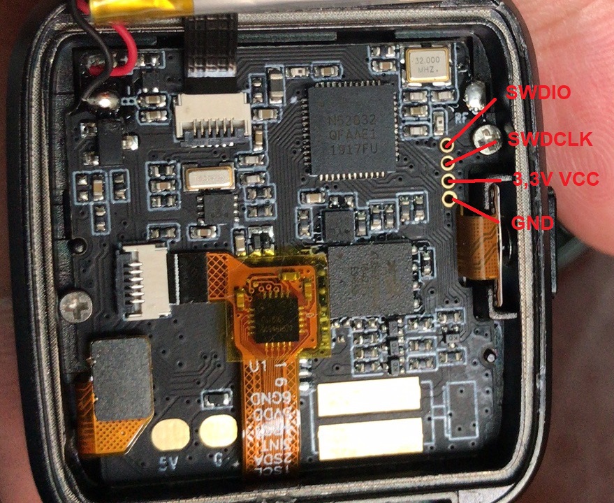
The dev kits have exposed SWD pins for flashing and debugging.
Only a few devs have soldered to these pins, most just use friction to make contact with the programming cable.
The pinout is:
Unlocking the Flash memory
Unlocking the device is a one-time action that is needed to enable to debug port and provide full access to the device. This will erase all existing software from the internal flash.
$ nrfjprog -f NRF52 --recover
Flashing
Using nrfjprog, flashing the PineTime is done with the command:
$ nrfjprog -f NRF52 --program firmware.hex --sectorerase
Debugging
Using Segger Ozone debugger, debugging and flashing is made easy.
Simply load the .elf file containing the final firmware and setup the debbuger to use SWD over USB for the chip nRF52832_xxAA. This setup can be done using the menu Tools/J-Link Settings. or by directly typing the following in the debugger console:
$ Project.SetDevice ("nRF52832_xxAA");
$ Project.SetHostIF ("USB", "");
$ Project.SetTargetIF ("SWD");
$ Project.SetTIFSpeed ("4 MHz");
$ File.Open ("path/to/your/build/zephyr/zephyr.elf");
