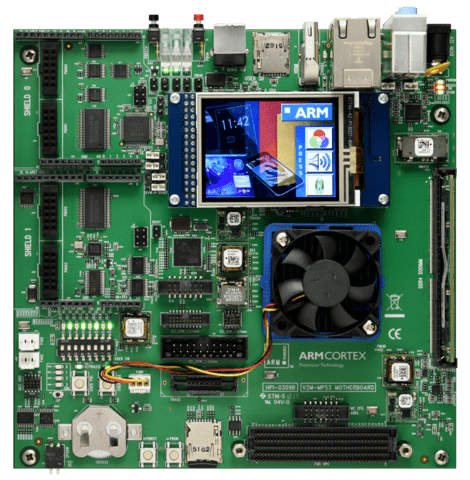
ARM MPS3 AN547
Overview
The mps3_an547 board configuration is used by Zephyr applications that run on the MPS3 AN547 board. It provides support for the MPS3 AN547 ARM Cortex-M55 CPU and the following devices:
Nested Vectored Interrupt Controller (NVIC)
System Tick System Clock (SYSTICK)
Cortex-M System Design Kit GPIO
Cortex-M System Design Kit UART
Ethos-U55 NPU

More information about the board can be found at the MPS3 FPGA Website.
Hardware
ARM MPS3 AN547 provides the following hardware components:
ARM Cortex-M55
Soft Macro Model (SMM) implementation of SSE-300 subsystem
Memory
8MB BRAM
4GB DDR4 SODIMM (by default, upgradeable to 8GB)
16GB eMMC
8MB QSPI Flash
Debug
P‐JTAG, F-JTAG, SWD, 4-bit trace, 16-bit trace
Four serial ports over USB
Interface
AHB GPIO
UART
SPI
I2C
I2S
Color LCD serial interface
Ethernet
VGA
On-board Peripherals
Color LCD
10 LEDs
8 Switches
2 user push buttons
Supported Features
The mps3_an547 board configuration supports the following hardware features:
Interface |
Controller |
Driver/Component |
|---|---|---|
NVIC |
on-chip |
nested vector interrupt controller |
SYSTICK |
on-chip |
systick |
UART |
on-chip |
serial port-polling; serial port-interrupt |
GPIO |
on-chip |
gpio |
Other hardware features are not currently supported by the port. See the MPS3 FPGA Website for a complete list of MPS3 AN547 board hardware features.
The default configuration can be found in the defconfig file:
boards/arm/mps3_an547/mps3_an547_defconfig.
For mode details refer to MPS3 AN547 Technical Reference Manual (TRM).
Serial Port
The MPS3 AN547 has six UARTs. The Zephyr console output by default, uses UART0, which is exposed over the Debug USB interface (J8).
Serial port 0 on the Debug USB interface is the MCC board control console.
Serial port 1 on the Debug USB interface is connected to UART 0.
Serial port 2 on the Debug USB interface is connected to UART 1.
Serial port 3 on the Debug USB interface is connected to UART 2.
Programming and Debugging
Flashing
MPS3 AN547 provides:
A USB connection to the host computer, which exposes Mass Storage and CMSIS-DAP, and serial ports.
Building an application
You can build applications in the usual way. Here is an example for the Hello World application.
# From the root of the zephyr repository
west build -b mps3_an547 samples/hello_world
Open a serial terminal (minicom, putty, etc.) with the following settings:
Speed: 115200
Data: 8 bits
Parity: None
Stop bits: 1
Reset the board, and you should see the following message on the corresponding serial port:
Hello World! mps3_an547
Uploading an application to MPS3 AN547
Applications can be in elf, hex or bin format. The binaries are flashed when the board boots up, using files stored on the on-board Micro SD card. The Motherboard Configuration Controller (MCC) is responsible for loading the FPGA image and binaries.
Connect the MPS3 to your host computer using the USB port. You should see a
USB connection exposing a Mass Storage (V2M-MPS3 by default).
The update requires 3 steps:
Copy application files to
<MPS3 device name>/SOFTWARE/.Open
<MPS3 device name>/MB/HBI0309C/AN547/images.txt.Update the
AN547/images.txtfile as follows:
TITLE: Versatile Express Images Configuration File

[IMAGES]
TOTALIMAGES: 1 ;Number of Images (Max: 32)

IMAGE0ADDRESS: 0x01000000 ;Please select the required executable program

IMAGE0FILE: \SOFTWARE\zephyr.elf
Reset the board, and you should see the following message on the corresponding serial port:
Hello World! mps3_an547