Important: We're excited to introduce our new technical documentation platform docs.nordicsemi.com, currently in Beta version. We invite you to explore it and share your feedback. Read more on our DevZone blog.
This door lock sample demonstrates the usage of the Matter application layer to build a door lock device with one basic bolt.
You can use this sample as a reference for creating your application.
This device works as a Matter accessory device, meaning it can be paired and controlled remotely over a Matter network built on top of a low-power 802.15.4 Thread or Wi-Fi network.
Support for both Thread and Wi-Fi depends on the hardware platform.
The door lock sample can be built with support for one transport protocol, either Thread or Wi-Fi, or with support for switching between Matter over Wi-Fi and Matter over Thread, where the application activates either Thread or Wi-Fi on boot, depending on the runtime configuration.
In case of Wi-Fi, this device works in the Legacy Power Save mode.
This means that the device sleeps most of the time and wakes up on each Delivery Traffic Indication Message (DTIM) interval to poll for pending messages.
The same distinction applies in the Thread and Wi-Fi switching scenario, depending on the active transport protocol.
If you want to commission the lock device and control it remotely through an IPv6 network, you also need a Matter controller device configured on PC or mobile.
This requires additional hardware depending on the setup you choose.
Note
Matter requires the GN tool.
If you are updating from the nRF Connect SDK version earlier than v1.5.0, see the GN installation instructions.
The development kits for this sample offer the following IPv6 network support for Matter:
Matter over Thread is supported for nrf52840dk_nrf52840, nrf5340dk_nrf5340_cpuapp, and nrf21540dk_nrf52840.
Matter over Wi-Fi is supported for nrf5340dk_nrf5340_cpuapp with the nrf7002ek shield attached (2.4 GHz and 5 GHz), for nrf7002dk_nrf5340_cpuapp (2.4 GHz and 5 GHz), or for nrf7002dk_nrf7001_nrf5340_cpuapp (2.4 GHz only).
The sample uses buttons for changing the lock and device states, and LEDs to show the state of these changes.
You can test it in the following ways:
Standalone, using a single DK that runs the door lock application.
Remotely over the Thread or the Wi-Fi protocol, which in either case requires more devices, including a Matter controller that you can configure either on a PC or a mobile device.
By default, the Matter accessory device has IPv6 networking disabled.
You must pair it with the Matter controller over Bluetooth® LE to get the configuration from the controller to use the device within a Thread or Wi-Fi network.
You have to make the device discoverable manually (for security reasons).
The controller must get the Onboarding information from the Matter accessory device and provision the device into the network.
For details, see the Commissioning the device section.
When built using the thread_wifi_switched build type and programmed to the nRF5340 DK with the nRF7002 EK shield attached, the door lock sample supports a feature that allows you to switch between Matter over Thread and Matter over Wi-Fi at runtime.
Due to Matter protocol limitations, a single Matter node can only use one transport protocol at a time.
The application is built with support for both Matter over Thread and Matter over Wi-Fi.
The device activates either Thread or Wi-Fi transport protocol on boot, based on a flag stored in the non-volatile memory on the device.
By default, Matter over Wi-Fi is activated.
You can trigger the switch from one transport protocol to the other using the Button 3 on the nRF5340 DK.
This toggles the flag stored in the non-volatile memory, and then the device is factory reset and rebooted.
Because the flag is toggled, the factory reset does not switch the device back to the default transport protocol (Wi-Fi).
Instead, the factory reset and recommissioning to a Matter fabric allows the device to be provisioned with network credentials for the transport protocol that it was switched to, and to start operating in the selected network.
You can program a portion of the application code related to the nRF70 Series’ Wi-Fi firmware onto an external memory to free up space in the on-chip memory.
This option is available only when building for the nRF5340 DK with the nRF7002 EK shield attached.
To prepare an application to use this feature, you need to create additional MCUboot partitions.
To learn how to configure MCUboot partitions, see the Adding nRF70 Series firmware patch partitions guide.
To enable this feature for Matter, set the CONFIG_NRF_WIFI_FW_PATCH_DFU Kconfig option to y for the application (in the application prj.conf) and the CONFIG_UPDATEABLE_IMAGE_NUMBER Kconfig option to 3 for the MCUBoot child image (in its own prj.conf).
The Matter implementation in the nRF Connect SDK lets you extend Bluetooth LE an additional Bluetooth LE service and use it in any Matter application, even when the device is not connected to a Matter network.
The Matter door lock sample provides a basic implementation of this feature, which integrates Bluetooth LE with the Nordic UART Service (NUS).
Using NUS, you can declare commands specific to a Matter sample and use them to control the device remotely through Bluetooth LE.
The connection between the device and the Bluetooth controller is secured and requires providing a passcode to pair the devices.
In the door lock sample, you can use the following commands with the Bluetooth LE with NUS:
Lock - To lock the door of the connected device.
Unlock - To unlock the door of the connected device.
If the device is already connected to the Matter network, the notification about changing the lock state will be send to the Bluetooth controller.
Currently, the door lock’s Bluetooth LE service extension with NUS is only available for the nRF52840 and the nRF5340 DKs in the Matter over Thread network variant.
However, you can use the Bluetooth LE service extension regardless of whether the device is connected to a Matter over Thread network or not.
The sample does not use a single prj.conf file.
Configuration files are provided for different build types, and they are located in the sample root directory.
Before you start testing the application, you can select one of the build types supported by the application.
Debug version of the application; can be used to enable additional features for verifying the application behavior, such as logs or command-line shell.
You can enable over-the-air Device Firmware Upgrade only on hardware platforms that have external flash memory.
Currently only nRF52840 DK, nRF5340 DK and nRF7002 DK support Device Firmware Upgrade feature.
The sample supports over-the-air (OTA) device firmware upgrade (DFU) using one of the two following protocols:
Matter OTA update protocol that uses the Matter operational network for querying and downloading a new firmware image.
Simple Management Protocol (SMP) over Bluetooth® LE.
In this case, the DFU can be done either using a smartphone application or a PC command line tool.
Note that this protocol is not part of the Matter specification.
In both cases, MCUboot secure bootloader is used to apply the new firmware image.
The DFU over Matter is enabled by default.
The following configuration arguments are available during the build process for configuring DFU:
To configure the sample to support the DFU over Matter and SMP, use the -DCONFIG_CHIP_DFU_OVER_BT_SMP=y build flag.
When building on the command line, run the following command with build_target replaced with the build target name of the hardware platform you are using (see Requirements), and dfu_build_flag replaced with the desired DFU build flag:
west build -b build_target -- dfu_build_flag
For example:
west build -b nrf52840dk_nrf52840 -- -DCONFIG_CHIP_DFU_OVER_BT_SMP=y
You can add support for the nRF21540 front-end module to this sample by using one of the following options, depending on your hardware:
Build the sample for one board that contains the nRF21540 FEM, such as nrf21540dk_nrf52840.
Manually create a devicetree overlay file that describes how FEM is connected to the nRF5 SoC in your device.
See Set devicetree overlays for different ways of adding the overlay file.
Provide nRF21540 FEM capabilities by using a shield, for example the nRF21540 EK shield that is available in the nRF Connect SDK.
In this case, build the project for a board connected to the shield you are using with an appropriate variable included in the build command, for example SHIELD=nrf21540ek.
This variable instructs the build system to append the appropriate devicetree overlay file.
To build the sample in the nRF Connect for VS Code IDE for an nRF52840 DK with the nRF21540 EK attached, add the shield variable in the build configuration’s Extra CMake arguments and rebuild the build configuration.
For example: -DSHIELD=nrf21540ek.
To build the sample from the command line for an nRF52840 DK with the nRF21540 EK attached, use the following command within the sample directory:
west build -b nrf52840dk_nrf52840 -- -DSHIELD=nrf21540ek
See Programming nRF21540 EK for information about how to program when you are using a board with a network core, for example nRF5340 DK.
Each of these options adds the description of the nRF21540 FEM to the devicetree.
See Working with RF front-end modules for more information about FEM in the nRF Connect SDK.
To add support for other front-end modules, add the respective devicetree file entries to the board devicetree file or the devicetree overlay file.
This sample supports one Bluetooth LE connection at a time.
Matter commissioning, DFU, and NUS over Bluetooth LE must be run separately.
The door lock’s Bluetooth LE service extension with NUS requires a secure connection with a smartphone, which is established using a security PIN code.
The PIN code is different depending on the build type:
In the debug build type, the secure PIN code is generated randomly and printed in the log console in the following way:
PROVIDE THE FOLLOWING CODE IN YOUR MOBILE APP: 165768
In the release build type, the secure PIN is set to 123456 due to lack of a different way of showing it on nRF boards other than in the log console.
In this sample, the factory data support is enabled by default for all build types except for the target board nRF21540 DK.
This means that a new factory data set will be automatically generated when building for the target board.
To disable factory data support, set the following Kconfig options to n:
Shows the overall state of the device and its connectivity.
The following states are possible:
Short Flash On (50 ms on/950 ms off) - The device is in the unprovisioned (unpaired) state and is waiting for a commissioning application to connect.
Rapid Even Flashing (100 ms on/100 ms off) - The device is in the unprovisioned state and a commissioning application is connected over Bluetooth LE.
Solid On - The device is fully provisioned.
LED 2:
Shows the state of the lock.
The following states are possible:
Solid On - The bolt is extended and the door is locked.
Off - The bolt is retracted and the door is unlocked.
Rapid Even Flashing (50 ms on/50 ms off during 2 s) - The simulated bolt is in motion from one position to another.
Additionally, the LED starts blinking evenly (500 ms on/500 ms off) when the Identify command of the Identify cluster is received on the endpoint 1.
The command’s argument can be used to specify the duration of the effect.
Button 1:
Depending on how long you press the button:
If pressed for less than three seconds:
If the device is not provisioned to the Matter network, it initiates the SMP server (Simple Management Protocol) and Bluetooth LE advertising for Matter commissioning.
After that, the Device Firmware Update (DFU) over Bluetooth Low Energy can be started.
(See Upgrading the device firmware.)
Bluetooth LE advertising makes the device discoverable over Bluetooth LE for the predefined period of time (15 minutes by default).
If the device is already provisioned to the Matter network it re-enables the SMP server.
After that, the DFU over Bluetooth Low Energy can be started.
(See Upgrading the device firmware.)
If pressed for more than three seconds, it initiates the factory reset of the device.
Releasing the button within a 3-second window of the initiation cancels the factory reset procedure.
Button 2:
Changes the lock state to the opposite one.
Button 3:
On the nRF5340 DK when using the thread_wifi_switched build type: If pressed for more than ten seconds, it switches the Matter transport protocol from Thread or Wi-Fi to the other and factory resets the device.
On other platform or build type: Not available.
SEGGER J-Link USB port:
Used for getting logs from the device or for communicating with it through the command-line interface.
After building the sample and programming it to your development kit, complete the following steps to test its basic features:
Connect the kit to the computer using a USB cable.
The kit is assigned a COM port (Windows) or ttyACM device (Linux), which is visible in the Device Manager.
Open a serial port connection to the kit using a terminal emulator that supports VT100/ANSI escape characters (for example, nRF Connect Serial Terminal).
See Testing and optimization for the required settings and steps.
Observe that LED 2 is lit, which means that the door lock is closed.
Press Button 2 to unlock the door.
LED 2 is blinking while the lock is opening.
After approximately two seconds, LED 2 turns off permanently.
The following messages appear on the console:
I: Unlock Action has been initiatedI: Unlock Action has been completed
Press Button 2 one more time to lock the door again.
LED 2 starts blinking and remains turned on.
The following messages appear on the console:
I: Lock Action has been initiatedI: Lock Action has been completed
Keep the Button 1 pressed for more than six seconds to initiate factory reset of the device.
The device reboots after all its settings are erased.
Before starting the commissioning to Matter procedure, ensure that there is no other Bluetooth LE connection established with the device.
To commission the device, go to the Testing Matter in the nRF Connect SDK page and complete the steps for the Matter network environment and the Matter controller you want to use.
After choosing the configuration, the guide walks you through the following steps:
Only if you are configuring Matter over Thread: Configure the Thread Border Router.
Build and install the Matter controller.
Commission the device.
Send Matter commands that cover scenarios described in the Testing section.
When you start the commissioning procedure, the controller must get the onboarding information from the Matter accessory device.
The onboarding information representation depends on your commissioner setup.
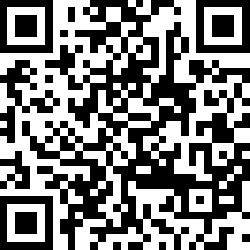
For this sample, you can use one of the following onboarding information formats to provide the commissioner with the data payload that includes the device discriminator and the setup PIN code:
Scan the following QR code with the app for your ecosystem:
MT:8IXS142C00KA0648G00
34970112332
When the factory data support is enabled, the onboarding information will be stored in the build directory in the following files:
The factory_data.png file includes the generated QR code.
The factory_data.txt file includes the QR Code Payload and the manual pairing code.
This data payload also includes test Device Attestation, with test Certification Declaration, Product ID, and Vendor ID.
These are used for Device Attestation within commissioning, and you can generate your own test Certification Declaration when you work on Matter end product.
You can only test Thread and Wi-Fi switching on the nRF5340 DK with the nRF7002 EK shield attached, using the thread_wifi_switched build type.
To test this feature, complete the following steps:
Build the door lock application using the thread_wifi_switched build type:
west build -b nrf5340dk_nrf5340_cpuapp -- -DCONF_FILE=prj_thread_wifi_switched.conf -DSHIELD=nrf7002ek -Dmultiprotocol_rpmsg_SHIELD=nrf7002ek_coex
Open a serial port connection to the kit using a terminal emulator that supports VT100/ANSI escape characters (for example, nRF Connect Serial Terminal).
See Testing and optimization for the required settings and steps.
Program the application to the kit using the following command:
west flash --erase
Wait until the device boots.
Find the following log message which indicates that Wi-Fi transport protocol is activated:
D: 423 [DL]Starting Matter over Wi-Fi
Press Button 3 for more than ten seconds to trigger switching from one transport protocol to the other.
Wait until the operation is finished and the device boots again.
Find the following log message which indicates that Thread transport protocol is activated:
Install nRF Toolbox on your Android (Android 11 or newer) or iOS smartphone (iOS 16.1 or newer).
Build the door lock application for Matter over Thread with the CONFIG_CHIP_NUS set to y.
For example, if you build from command line for the nrf52840dk_nrf52840, use the following command:
west build -b nrf52840dk_nrf52840 -- -DCONFIG_CHIP_NUS=y
Program the application to the kit using the following command:
west flash --erase
If you built the sample with the debug build type, connect the board to an UART console to see the log entries from the device.
Open the nRF Toolbox application on your smartphone.
Select Universal Asynchronous Receiver/Transmitter UART from the list in the nRF Toolbox application.
Tap on Connect.
The application connects to the devices connected through UART.
Select MatterLock_NUS from the list of available devices.
The Bluetooth Pairing Request with an input field for passkey appears as a notification (Android) or on the screen (iOS).
Depending on the build type you are using:
For the release build type: Enter the passkey 123456.
For the debug build type, complete the following steps:
Search the device’s logs to find PROVIDETHEFOLLOWINGCODEINYOURMOBILEAPP: phrase.
Read the randomly generated passkey from the console logs.
Enter the passcode on your smartphone.
Wait for the Bluetooth LE connection to be established between the smartphone and the DK.
In the nRF Toolbox application, add the following macros:
Lock as the Command value type Text and any image.
Unlock as the Command value type Text and any image.
Tap on the generated macros and observe the LED 2 on the DK.
The Bluetooth LE connection between a phone and the DK will be suspended when the commissioning to the Matter network is in progress or there is an active session of SMP DFU.
To read the current door lock state from the device, read the Bluetooth LE RX characteristic.
The new lock state is updated after changing the state from any of the following sources: NUS, buttons, Matter stack.