 |
nRF51 SDK - S110 SoftDevice
|
|
nRF51 SDK - S110 SoftDevice
|
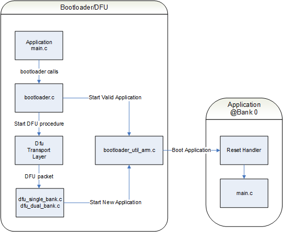
The Bootloader/DFU example makes it possible to receive a SoftDevice, Bootloader, and Application image and write it to the internal flash of the nRF51.
The image can be transferred over BLE or using serial wire (HCI/UART).
During system start-up, the Bootloader/DFU will be started and during start-up it will determine if a valid application is present in bank 0. Location of bank 0 is following the location of SoftDevice. For SoftDevice v7.1.0, this address is 0x00016000 (see also Dual Bank Flash Layout for detailed description). If a valid application is present in Bank 0 the Bootloader will start the application, otherwise the Bootloader will be in DFU mode expecting a Device Firmware Update. If it is desired to put a device with an existing application, restart with device with Button 7 pressed.
A schematic overview of the blocks in Bootloader/DFU is seen in Figure 1.
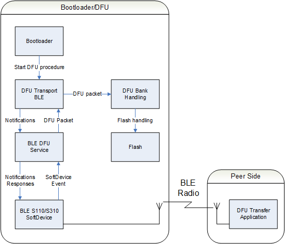
The Bootloader/DFU supports transferring of an image using BLE.
The DFU BLE Transport uses a BLE Service for data transfer (see Device Firmware Update BLE Service). The BLE DFU Service relies on S110 SoftDevice for data transfer. The DFU Bank Handling will ensure the writing of received data packets to flash.
Figure 2 shows a schematic overview of the Bootloader/DFU project with BLE Support.
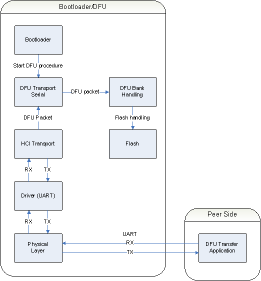
The Bootloader/DFU supports transferring of an image using HCI over UART. HCI Transport layer over UART is used for increased robustness of the transfer. A detailed description of HCI is found in HCI Transport.
The DFU Bank Handling will ensure the writing of received data packets to flash.
Figure 3 shows a schematic overview of the Bootloader/DFU project with UART Support.
The DFU bootloader has an internal state machine independent of the transport layer used. All initializing and writing to non-volatile memory is controlled by the DFU module.
Figure 3 illustrates the transitions in the state machine:
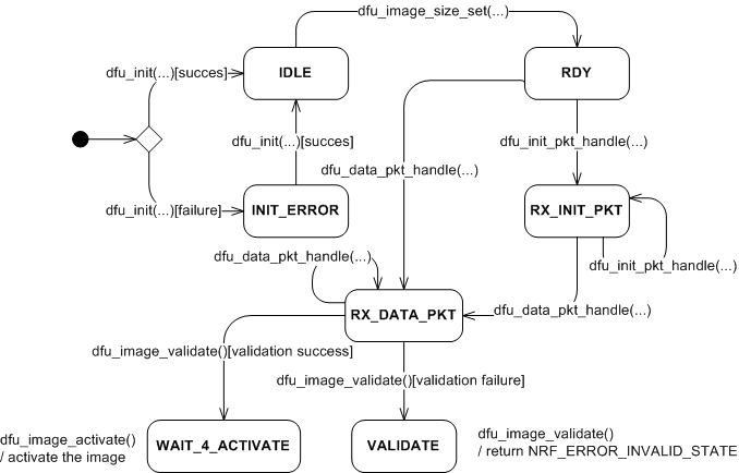
Entry point indicates that the bootloader is started up, and would initialize the DFU. In this initialization the DFU would prepare the non-volatile memory region for the new application. Either using all available memory overwriting the old image, or using banked memory where the old application is retained until a new application is uploaded and validated. Also the selected transport layer would be initialized in this phase.
| Message type | Description |
|---|---|
| - dfu_init | Message initializing the Device Firmware Update module. |
| - dfu_image_size_set | Message setting the DFU image size. |
| - dfu_data_pkt_handle | Message containing a portion of the new application. |
| - dfu_init_pkt_handle | Message for optional customer specific data. |
| - dfu_image_validate | Message triggering validation of the new application. |
| - dfu_image_activate | Message activating the transferred image after validation has successfully completed |
| - dfu_sys_reset | Can occur any time, making the DFU go into a reset of the chip. A bootloader time-out or an external message can trigger the system reset. |
 1.8.3.1
