 |
nRF51 SDK - S110 SoftDevice
|
|
nRF51 SDK - S110 SoftDevice
|
In case the device has an existing application image, it may be most desired (provided device has enough resources) to restore the older/existing application image in event the device firmware update either did not succeed or could not be completed. Through out the description for the DFU examples, a bootloader that is capable of preserving the existing application while receiving a new image is referred to as a 'dual bank' update. While the bootloader that is not capable of preserving an existing application once new image update has started is referred to as 'single bank' update. See also Bootloader/DFU Flashing to understand flash access operations better.
The DFU Bootloader project uses a memory layout similar to the of the nRF51822 Bluetooth examples, except that the memory region from 0x3C000-0x40000 has been reserved for the DFU Bootloader, and application data is written below the bootloader instead of at the end of the flash. The memory layout can be seen in Figure 1.
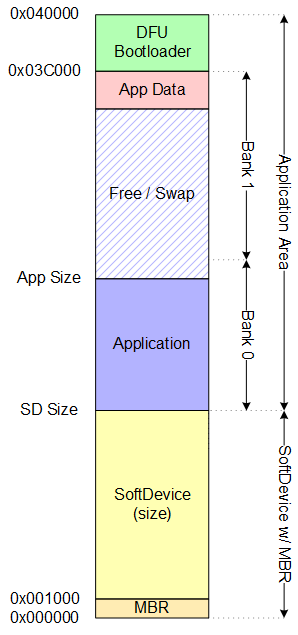
The table below lists the memory ranges when using a SoftDevice. The SoftDevice will be using region 1 memory spanning from address 0x0 to 0x16000. Region 1 will contain the application and bootloader.
| Memory Range | Usage |
|---|---|
| 0x0003C000 - 0x00040000 | DFU Bootloader and data |
| 0x00016000 - 0x0003C000 | Application Code (BANK 0), Free / Swap (BANK 1), and data |
| 0x00001000 - 0x00016000 | SoftDevice |
| 0x00000000 - 0x00001000 | Master Boot Record (MBR) |
The Application Data size is default set to 0x0000, meaning that all Application Data will be erased during a Device Firmware Update procedure. This behaviour can be configured by the developer to ensure persistency of the Application Data by specifying:
to a different value. Specifying DFU_APP_DATA_RESERVED to 0x1000 will ensure that 4 pages of Application Data are preserved during the DFU procedure.
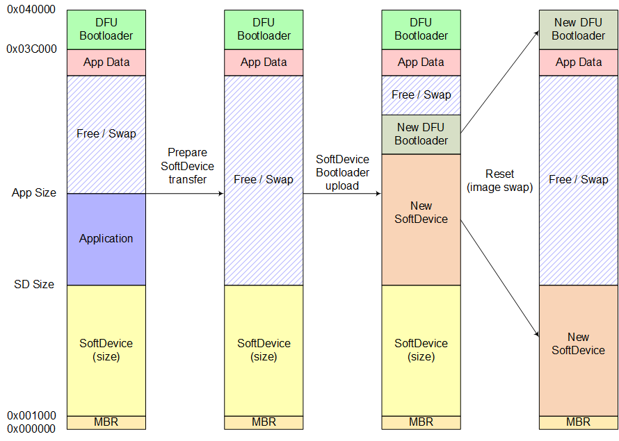
The steps of transferring a new SoftDevice (with/without Bootloader) is illustrated in the figure below.
| Detailed description | |
|---|---|
| Step 1 | Start DFU packet received, SoftDevice (Code: 0x01) or SoftDevice with Bootloader (Code: 0x03). Current application will be erased to prepare for new SoftDevice. |
| Step 2 | DFU Data packets with SoFtDevice image are received. |
| Step 3 | Data transmission completed and image is validated. System resets and replace current SoftDevice (and Bootloader) with newer versions. |
The steps of the Application or Bootloaderr update procedure are illustrated in the figures below.
| Detailed description | |
|---|---|
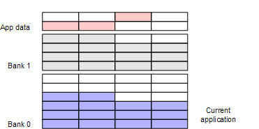
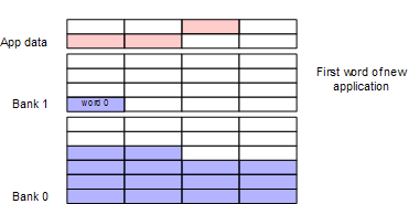
| Figure 3 | Before the Bootloader initializes, the active Application resides in Bank 0, while the content of Bank 1 is undefined. |
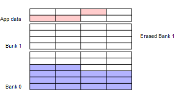
| Figure 4 | As a first step the Bootloader erases Bank 1, where the received new Application will be copied. This ensures that if the update is interrupted the old Application is still available. |
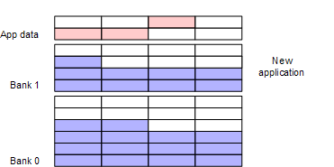
| Figure 5 | During transfer the received packets of the new Application are written into Bank 1. It is assumed that the packets are transmitted in the right order. |
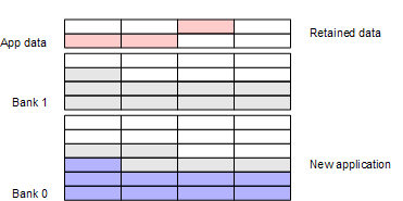
| Figure 6 | After all packets of the new Application are received, both the old and the new Application are present in the memory. This ensures that fallback to the old Application is possible if the new Application cannot be activated. |
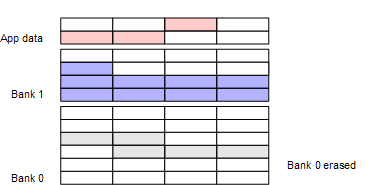
| Figure 7 | If the activation of the new Application is successful, Bank 0 is erased to accommodate the new Application. If DFU_APP_DATA_RESERVED is set, Application Data will be preserved. |
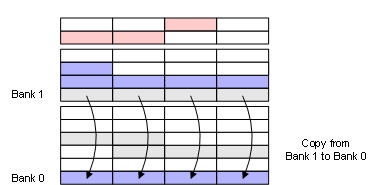
| Figure 8 | As part of of activating the new Application it is moved from Bank 1 to Bank 0. |
| Figure 9 | After the copy procedure is complete, the system can be reset with running the new Application in Bank 0. Bank 1 won't be erased until the Bootloader initializes again. |
| Figure 10 | If Application Data from the old Application was preserved, the new Application will append any new data written. |

The DFU Bootloader project uses a memory layout similar to the of the nRF51822 Bluetooth examples, except that the memory region from 0x3C000-0x40000 has been reserved for the DFU Bootloader, and application data is written below the bootloader instead of at the end of the flash.
The memory layout can be seen in Figure 1.
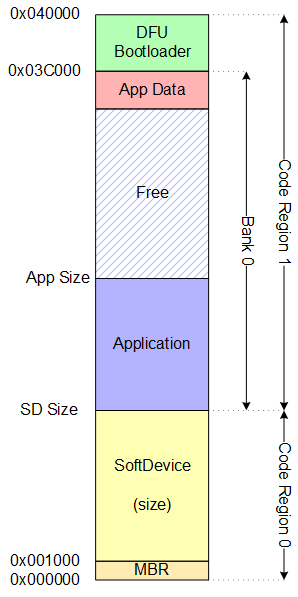
The table below lists the memory ranges when using a SoftDevice. The SoftDevice will be using region 1 memory spanning from address 0x0 to 0x16000. Region 1 will contain the application and bootloader.
| Memory Range | Usage |
|---|---|
| 0x0003C000 - 0x00040000 | Code Region 1: DFU Bootloader and data |
| 0x00016000 - 0x0003C000 | Code Region 1: Application Code (BANK 0) and data |
| 0x00000000 - 0x00016000 | Code Region 0: SoftDevice |
Code region 1 size will depend on the size of the SoftDevice used. For this example, with a 256kB version of the nrf51 the stack uses 84kB leaving 172kB to the bootloader and the application.
The region is then divided into 3 sub-regions:
The bootloader projects in the SDK have memory reserved for the bootloader and the bootloader settings data. The memory reservation can easily be modified in the project files to match the final size of the bootloader. For the example bootloader provided, the application will get a total of 172kB - 16kB = 156kB. The available memory for an application would be 172kB - (application save data).
The Application Data size is default set to 0x0000, meaning that all Application Data will be erased during a Device Firmware Update procedure. This behaviour can be configured by the developer to ensure persistence of the Application Data by specifying:
to a different value. Specifying DFU_APP_DATA_RESERVED to 0x1000 will ensure that 4 pages of Application Data are preserved during the DFU procedure.
Memory Layout
When using Full Memory Layout the bootloader will erase the whole application region (BANK 0) when entering the bootloader mode. The application save data will not be modified. During DFU data transfer each word received by the bootloader will be written to BANK 0 without any buffering.
When DFU validation is performed the written flash in BANK 0 will be validated and the bootloader will write its settings data and perform a system reset.
During start-up the bootloader will read its settings, to see if chip contains a valid application image. If an invalid image was received, the bootloader will start the update sequence as if has never been done. On the other hand, if an valid image was received, it will start the application located in BANK 0.
The steps of the update procedure are illustrated in the figures below.
| Detailed description | |
|---|---|
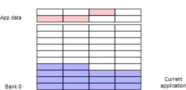
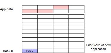
| Figure 2 | Before the Bootloader initializes, the active Application resides in Bank 0. |
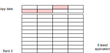
| Figure 3 | Upon receiving the Start packet the Bootloader erases Bank 0. If DFU_APP_DATA_RESERVED is set, Application Data will be preserved. |
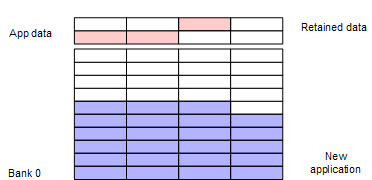
| Figure 4 | During transfer the received packets of the new Application are written into Bank 0. It is assumed that the packets are transmitted in sequential order. |
| Figure 5 | After the copy procedure is complete, the new Application can be activated. If activation is successful, the system can be reset with running the new Application in Bank 0. If the new Application cannot be activated, the Bootloader will be started after reset until a working image is received. |
| Figure 6 | If Application Data from the old Application was preserved, the new Application will append any new data written. |

 1.8.3.1
