 |
nRF51 SDK
|
|
nRF51 SDK
|
User Guide for Gazell Link Layer library. More...
The Gazell Link Layer is a protocol for setting up a robust wireless link between typically one single Host and up to eight Devices in a star network topology. The Gazell Link Layer is a protocol designed to minimize power consumption in power-sensitive wireless desktop products and is also suitable for a range of other wireless applications.
In the rest of this text we will replace "Gazell Link Layer" simply with "Gazell".
Gazell takes advantage of the fact that one end of the communication can be "always on" in order to minimize the power consumption of the power-sensitive devices on the other end. The prototypical example of this is a wireless mouse communicating with a USB dongle. Moreover, Gazell has a sophisticated but easy-to-use channel switching and synchronization scheme, that gives robustness to interference and good wireless coexistence properties while still enabling high-throughput and low latency.
Gazell supports a star network, where each node has a mode determining its role; one node is in Host mode and is "always on" while the remaining nodes are in Device mode. Each Gazell Host can communicate with up to 8 Gazell Devices. Each Device communicates to a single Host.
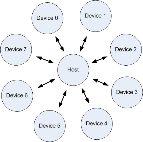
Once enabled, the Host in a Gazell network is always listening, and it is the Device that always initiates a communication. Each packet that a Device sends is required to be acknowledged by the Host. It is possible for the Host to send data to the Device by piggybacking data to an acknowledgement (ACK) packet. Therefore a Host has to wait for a packet from a Device before it can send any data to it.
It is possible to build more sophisticated Gazell networks, since a single Device is able to speak to several Hosts and any node is able to change between the two modes. However, this requires the application to coordinate such a network. Therefore, we focus here on the typical use-case as a star network with static modes.
Gazell handles automatically all synchronization and packet handling. All the user is required to do is to add payloads to the transmit (TX) FIFOs and read payloads from the receive (RX) FIFOs. Gazell automatically notifies the application when a packet is received.
The typical Gazell application has the following steps:
Gazell can also be disabled at any time using the nrf_gzll_disable() function. When this is called Gazell will complete any ongoing transmission or reception before being disabled (That is, until the end of the current timeslot, a concept we explain later in the section on Timeslots). When the disabling operation is complete, Gazell will call the nrf_gzll_disabled() function. By the time this callback is made, the Gazell CPU context, radio and Gazell timer will have stopped. It is now possible to call any of the configuration set functions, which will be in force, once Gazell is enabled again.
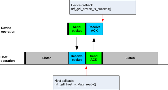
A typical packet transaction between a Device and a Host consists of a Device initiating the transaction by sending a data packet to the Host after which the Host sends an ACK packet in return.
When an ACK packet is received by the Device, it knows that the initial packet was successfully transmitted and the nrf_gzll_device_tx_success() callback function will be called to notify the application of this.
Similarly, when the initial packet is received by the Host, the nrf_gzll_host_rx_data_ready() callback function will be called to notify to the application that a new packet has been received.
Note that these callback functions are actually queued so that the application avoids race conditions. This is discussed later in the section Callback queueing.
A transaction can fail, because either:
If a transaction fails the Device will attempt to retransmit the initial packet to the Host until the ACK is finally received or the maximum number of transmission attempts is reached. If the maximum number of transmission attempts is reached the retransmissions will stop and the nrf_gzll_device_tx_failed() callback will be called.
In the case where only the ACK packet sent from the Host to the Device is lost, but both the initial packet and the subsequent retransmission attempts are being successfully received by the Host, the repeated packets will be discarded by the Host, but the ACK packets will still be sent in return to the Device. This prevents the application receiving duplicate data packets at the Host.
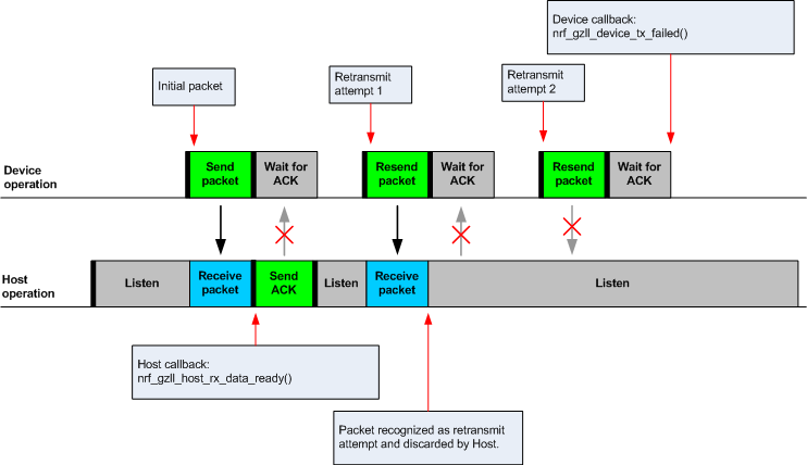
Any packet transmitted from a Device to a Host is uniquely identified by a two bit packet ID field in the packet header together with the packet's 16-bit Cyclic Redundancy Check (CRC). This packet ID is used to distinguish a new packet from the previous packet if it has the same payload.
At the Host, retransmitted packets will be discarded and not added to an RX FIFO.
All eight pipes on both the Device and the Host have two First-in First-out (FIFO) buffers that can hold packets. We call these FIFO buffers simply FIFOs. Each pipe has a TX FIFO and an RX FIFO.
When Gazell is enabled in Device mode, any packets uploaded to a TX FIFO will be transmitted at the next opportunity. If several TX FIFOs contain packets, the various TX FIFOs will be serviced in a round robin fashion, meaning that no TX FIFOs will experience starvation even when packets are continuously being added to other TX FIFOs.
When an ACK is successfully received from a Host, it implies that the payload was successfully received and added to the Host's RX FIFO, the successfully transmitted packet will be removed from the TX FIFO so that the next packet in the FIFO can be transmitted.
If an ACK received by a Device contains a payload, this payload will be added to the pipe's RX FIFO.
If the RX FIFO for a specific pipe on a Device is full and can not accommodate any new packets, no new packets will be sent from the Device on this pipe. In this case, we will never end up in the situation where a payload received in an ACK will have to be discarded due to the pipe's RX FIFO being full.
In addition, Gazell limits the total number of packets in the FIFOs, which is smaller than the total size of all the FIFOs. Therefore, a Device will also refuse to add a packet to the TX FIFO if it doesn't have space for the packet as well as the corresponding ACK.
When Gazell is enabled in Host mode, all enabled pipes (addresses) are simultaneously monitored for incoming packets.
If a new packet not previously added to the pipe's RX FIFO is received, and the pipe's RX FIFO has available space for the packet, the packet will be added to the RX FIFO and an ACK will be sent in return to the Device. If the pipe's TX FIFO contains any packets, the next serviceable packet in the TX FIFO will be attached as a payload in the ACK packet. In order for a TX packet to be attached to an ACK, this TX packet would have to be uploaded to the TX FIFO before the packet is received.
As we can not ensure that the ACK always will be successfully received by the Device, the data payload added to the ACK will not be removed from the TX FIFO immediately. This TX packet will be removed from the TX FIFO when a new packet (new packet ID or CRC) is received on the same pipe. In this case, the new packet sent as an ACK will serve as a kind of acknowledgement from the Device saying that the previous ACK from the Host was successfully received by the Device. ACKs sent in reply to retransmission attempts will all contain the same TX payload.
When the Host is handling packets on multiple pipes, care needs to be taken to ensure that ACK payloads in the TX FIFOs on pipes that are no longer in use, are not taking up space in the memory pool and consquently blocking communication on other pipes. To avoid such congestion, the application on the Host can flush the TX FIFOs on the pipes no longer in use.
Gazell contains an internal callback queue for queueing pending callbacks in the case where Gazell attempts to call a new callback function while the application is already servicing a previously called callback function.
As an example, if a new packet is being received by a Host while the application is already servicing the nrf_gzll_host_rx_data_ready() callback from a previously received packet, the nrf_gzll_host_rx_data_ready() callback for the latest packet will be added to the callback queue and serviced at a later opportunity. In this case, nrf_gzll_host_rx_data_ready() will be called one time for every received packet, and the application does not need to handle the potential race condition scenario where a new packet is being received just before the application is about to exit the nrf_gzll_host_rx_data_ready() function.
Similarly, on a Device the nrf_gzll_device_tx_success() callback will be called one time for every packet receiving an ACK, even when a new packet is receiving an ACK while the application is servicing the nrf_gzll_device_tx_success() callback of a previously transmitted packet.
The size of the callback queue is given by NRF_GZLL_CONST_CALLBACK_QUEUE_LENGTH.
A core parameter in Gazell is the timeslot. The timeslot can be seen as the internal Gazell "heartbeat".
In a Device, any packet transmission (both new packets and retransmitted packets) will start at the start of a timeslot, and only one packet transaction (including ACK) can take place within a timeslot.
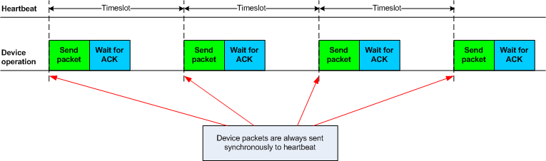
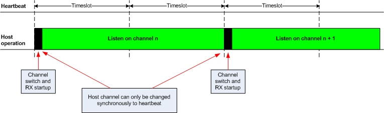
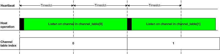
And similarly, in a Host, the RF channel only changes at the start of a timeslot.
The period for the heartbeat is set using the nrf_gzll_set_timeslot_period() function.
To ensure good coexistence performance with other radio products operating in the same 2.4 GHz frequency band as Gazell, such as Wi-Fi or Bluetooth, Gazell implements mechanisms for hopping between various radio frequency channels.
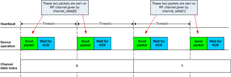
When enabled, Gazell will pick channels from a predefined channel table.
The contents and size of this channel table can be reconfigured by the application, however the Device and Host should be configured to have the exact same channel table. In total the application can pick from a full channel set of 80 channels when specifying the channel table. Normally, a channel table of 3-7 channels has shown to give a satisfactory coexistence performance in most environments.
Having a too large channel table may increase the transmission latency and power consumption, while using a too small channel table may decrease the coexistence performance.
The core parameters deciding the channel hopping behavior are:
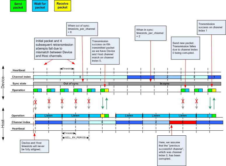
Which one being used depends on whether Gazell is "in sync" or "out of sync" (these terms are closer described in the Synchronization section). Therefore, we will not differentiate between these two terms and use the term timeslots_per_channel instead.
The timeslots_per_channel parameter decides the number of timeslots Gazell shall reside on a single channel before the channel shall be changed. When the next timeslot where a channel shift is performed, Gazell will pick the next channel from the predefined channel table, cycling back to the start of the channel table if required.
In Device mode, timeslots_per_channel can also be seen as the number of transmission attempts to be spent on each channel before switching channel. This is because there is at most one transmission attempt for every timeslot.
The channel_selection_policy parameter is used by a Device being in sync to decide the initial channel to be used when sending a new packet to a Host (that is for the very first packet being sent, not for any following retransmission attempts).
Once synchronized with the Host, the Device can send either on the current channel that it believes the Host is on or on the last successful channel. This can be configured using the nrf_gzll_set_device_channel_selection_policy().
This channel_selection_policy parameter can take the following two values:
By choosing the NRF_GZLL_DEVICE_CHANNEL_SELECTION_POLICY_USE_SUCCESSFUL policy, the Device will start sending packets on the channel it last had a successfully acknowledged transmission. This policy is the most robust against static interferers as once the Device finds a quiet channel it should be able to successfully communicate with the Host.
By choosing the NRF_GZLL_DEVICE_CHANNEL_SELECTION_POLICY_USE_CURRENT policy, the Device sends on the channel it believes the Host is currently listening to. This achieves the lowest latency and highest throughput of the two policies as the Device does not have to wait for the Host to be listening on a specific channel. This policy is frequency hopping. The disadvantage of this policy is that if there is a static interferer on a particular channel, the Device will waste packets attempting to send on this channel. Note that the application can reconfigure the channel table during runtime to overcome this.
As mentioned, the channel selection policy only applies for the initial transmitted packet. If transmission of this initial packet fails, the following retransmission attempts will always be sent at the channel the Device beleievs the Host is monitoring.
If Gazell is "out of sync", Gazell will always start the packet transmission immediately using the previous successful transmission channel. If Gazell has never before transmitted a successful packet and thus has no "previous successful channel" to relate to, Gazell will start using the first channel in the channel table.
The internal timeslot, or "heartbeat", mechanism of Gazell is used to obtain synchronous communication while still enabling efficient channel switching. This mechanism is useful when a Device needs to switch to a new channel in the case when radio interference is being experienced on the current channel.
Each Gazell Device has two synchronization states: "in sync" and "out of sync".
On the Host, the internal "heartbeat" timer will always be running when Gazell is enabled, independent of the Devices' synchronization state.
Before any packets have been successfully received and acknowledged, the Device is out of sync. In this state, the Device switches channel determined by the timeslots_per_channel_when_device_out_of_sync. The Device switches channel at a slower rate than the Host (as determined by timeslots_per_channel) in order that the Device will eventually transmit a packet on the same channel that the Host is on.
When a Device successfully transmits a packet, that is when an ACK packet is received from the Host, the Device will enter "in sync" state, as it now has the information needed for continuing to "guss" the following channels the Host will be listening to.
For knowing when to change channel, Gazell has an internal channel_index counter counting the number of timeslots Gazell resides on a single channel. When this counter reaches the maximum number of timeslots, as given by timeslots_per_channel, the channel_index counter is reset and the channel is changed. This channel_index counter is always reset when a ACK is being received, as the Device by receiving the ACK knows the channel being used by the Host, but it can not know the channel_index counter state on the Host. As a result, it is only for the timeslots where the channel_index counter equals zero a Device can be confident that it "guesses" the correct channel that a Host is monitoring. Therfore, a new Device transmission can only be started when the channel_index counter on the Device is zero. Retransmission attempts, however, can be sent on all timeslots.
Once the Device is in sync it will keep an internal timer running in order to maintain the internal heartbeat in order to remain synchronized with the Host. The duration that the Device will stay in the in sync state is the sync_lifetime and is measured in timeslots. The sync_lifetime is reset whenever a packet is received. Once the sync_lifetime has expired on a Device, the internal timer is stopped and the Device will return to being out of sync.
Note that, whenever a Device that is "in sync" sends a packet but does not receive an ACK it will continue transmitting maximum number of transmit attempts are reached.
By setting the sync_lifetime to zero, the Device will never be in sync. The sync_lifetime should be chosen with regard to how often packets are required to be sent and the fact that synchronization can only be maintained for a finite time due to clock drift and radio interference. The sync lifetime is configured using nrf_gzll_set_sync_lifetime().
The Device can know that sync has been achieved when the number of retransmissions gets close to zero. The nrf_gzll_device_tx_info_t structure is passed to the Device callback functions, and contains the number of transmit attempts required for the current packet. In addition, the nrf_gzll_device_tx_info_t contains the num_channel_switches parameter which can be used by the application to determine whether the RF channels are reliable.
Each Gazell node uses the term "pipe" as a logical address for communication with another node. Each pipe maps to one actual physical on-air address used when transmitting or receiving packets.
The actual on-air physical addresses are composed of a 2-4 byte long "base address" in addition to a 1 byte prefix address. The most significant byte of the base address is the first byte on the air. Note that the nRF51 radio uses an alternating sequence of 0s and 1s as the preamble of the packet. Therefore for packets to be received correctly, the most significant byte of the base address should not be an alternating sequence of 0s and 1s i.e. it should not be 0x55 or 0xAA.
Pipe 0 has its own unique base address, which is base address 0, while pipe 1-7 use the same base address, which is base address 1. This structure allows new nodes to pair use a shared address to initiate a new Device-Host link and then shift to a different address to continue communication. The base addresses are provided to the configuration functions as 32-bit unsigned integers with the least significant bytes being used.
Each of the 8 pipes have unique byte-long prefix address.
Gazell makes use of the following resources and requires exclusive access to them in order for Gazell to ensure correct operation:
The radio and timer interrupt handlers run at priority level 0 (highest level), and the Gazell callback functions run at priority level 1. Applications should run at priority level 2 or higher in order to ensure correct operation.
Gazell can be customized at runtime for a range of different applications. See the Application Programming Interface (API) for a list of configuration functions as well as the default and constant parameters. Note that editing the header file containing the default and constant parameters DOES NOT change their value when compiling a new project. These values are provided as a useful reference when making application with the precompiled library.
The Gazell Link Layer examples are not fully "out of the box" compatible with the legacy Gazell examples provided in the nRFgo SDK for nRF24Lxx devices. The default timeslot period and channel tables require adjustment, as well some setup to emulate the Gazell modes. Note that the Gazell "Low Power Host mode" (Host mode 1) is not supported in the nRF51.
The default channel tables require adjustment.
To change these values:
The Gazell Link Layer supports the following minimum timeslot periods.
In addition, the relation between the Device and Host timing parameters should be as follows:
To change these values:
The Gazell Link Layer protocol for the nRF51 series is compatible with the most useful modes of the Gazell Link Layer for the nRF24Lxx devices.
The legacy "Device mode 2" can be emulated as follows:
The legacy "Host mode 0" has the following behavior:
This behavior can be obtained the using the code snippet below. Here, we assume we have a channel table my_channel_table[] containing 3 channels.
This can be achieved using the following code snippet on the Device: