 |
nRF51 SDK
|
|
nRF51 SDK
|
Example proprietary profile used to update firmware (application image) file using Bluetooth Low Energy. This is not a standard profile, and is defined by Nordic to demonstrate how a typical Device Firmware Update can be achieved.
The Device Firmware Update (DFU) Profile is used to transfer an application image from a BLE master (example, PC or Smart Phone) to a slave (example, Heart Rate Sensor) that supports Device Firmware Updates using the DFU Service.
This profile requires the Generic Attribute Profile (GATT).
The profile defines two roles: DFU Target and Client. The DFU Target is the device which receives an image from the DFU Controller.
The following diagram shows the relationships between services and the two profile roles.
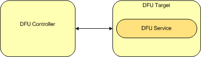
A DFU Target instantiates one instance of the DFU service.
The DFU Controller shall support the Device Firmware Update Service.
| Service | DFU Controller |
|---|---|
| Device Firmware Update Service | M |
The DFU Controller shall also be tolerant when receiving the following ATT Error Code defined in CSS Part B, Section 1.2 of Supplement to the Bluetooth Core Specification, Version 3 or later:
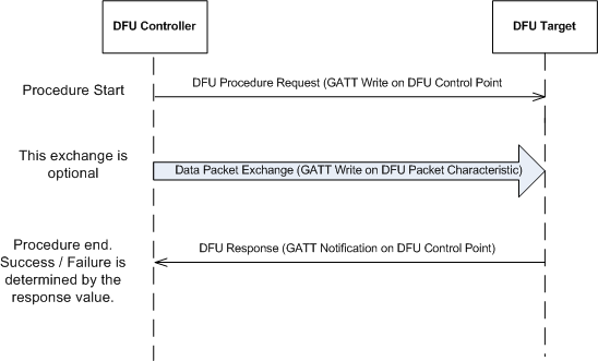
The DFU Controller requests one of the procedures defined for Device Firmware Update using the DFU Control Point. Each procedure requested by the Controller is characterised by a request on the DFU Control Point, using the GATT Write Procedure. This may be followed by additional writes on the DFU packet characteristic based, followed by end of procedure marked by a response from the DFU Target for the procedure using GATT Notifications on the Control Point. Response code in the response packet determines the success or failure of the procedure. In case of failure, the response codes provide an indication on possible reason for failure. Refer to the detailed description for more details in the DFU Control Point. The DFU Target process one request at a time, therefore if a request is received on the Target when already processing one, an ATT Error Response with 'Procedure Already In Progress' is received on the DFU Controller. Asynchronous Status and Image Size received information are sent by the DFU Target as GATT Notifications on the control point.
Below is small MSC to show a typical DFU Control Point Procedure
DFU Procedures defined are listed below:
| DFU Procedure | Description |
|---|---|
| Start DFU | Procedure to prepare the device for a uploading the firmware. Size of firmware is provided in the request parameter. DFU Target response determines the device is ready for next stage of firmware update. |
| Receive Init Data | Procedure to exchange information necessary for firmware update that needs to exchanged before upload of firmware. Hash exchange/ Public key Exchange etc are some examples of such information. |
| Receive App Data | Procedure to upload firmware fragmented as DFU Packets. Maximum size of each packet is (ATT_MTU - 3) octets. DFU Packets can be of variable length with a minimum size of 1 octet. |
| Validate | Procedure to validate updated firmware image. |
| Activate Image & Reset | Procedure to activate the new firmware and restart the device with new firmware. This procedure results in a GAP Disconnect. |
| System Reset | Procedure to reset system. This procedure result in a GAP Disconnection Procedure. |
| Report Received Image Size | Procedure to request the size of image received. |
| Packet Receipt Notification | Procedure to request notification on receiving every 'n' packets. The number 'n' is requested by the controller. This is not a mandatory procedure for the Controller. |
DFU Target in DFU mode, is in GAP General Discoverable mode and is connectable. 128-bit DFU Service UUID is advertised in the Advertisement Data, along with full name of DfuTarg.
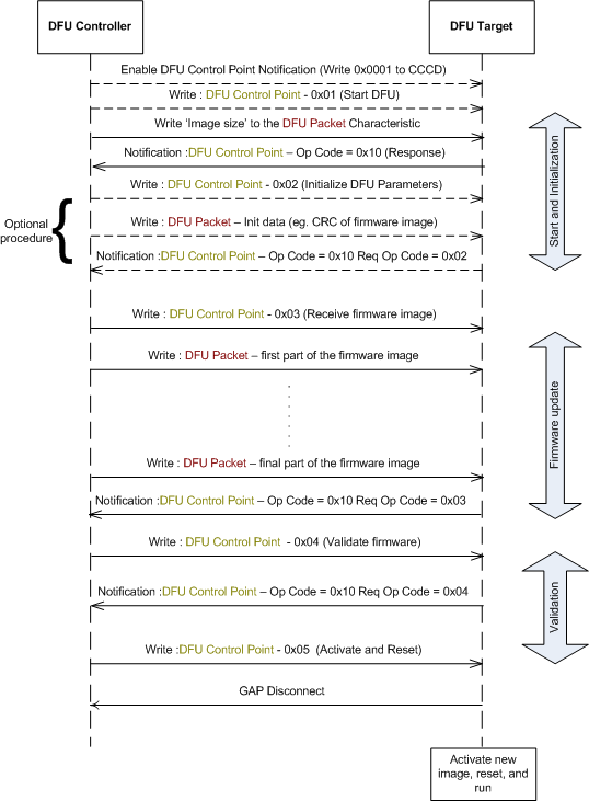
Once connected to the DFU Controller, DFU Procedure can be started by requesting a Start DFU Procedure. Size of new firmware is provided during this procedure. On successful Start DFU procedure, Receive Init Data is initiated to exchange CRC information. On success, this procedure is followed by upload of new firmware by requesting the Receive App Data Procedure. Currently, banked update is performed, implying, the old firmware can be restored in case firmware update procedure did not succeed at any stage of DFU Transfer. New firmware transferred is validated using the Validate Procedure. Validated firmware can be activated by issuing the Activate Image & Reset Procedure. It is possible to reset the system at any stage using the System Reset procedure. When this procedure is requested, the system will restart with old firmware in case the device had a firmware; in case the device did not have any existing application firmware the system will restart in DFU mode.
Firmware being updated is expected in binary format. It is possible to request the size of received firmware by requesting the Report Received Image Size procedure. This procedure is particularly useful on reconnection after a link loss. See Link Loss Procedure for more details. It is also possible for the Controller to request notification of acknowledge for every 'n' packets received using the Packet Receipt Notification procedure.
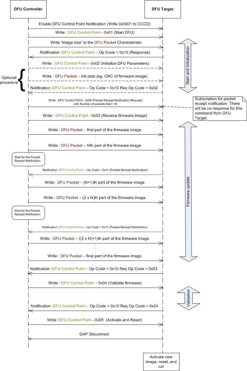
MSC below describes a typical firmware update exchange between a DFU Controller and DFU Target.
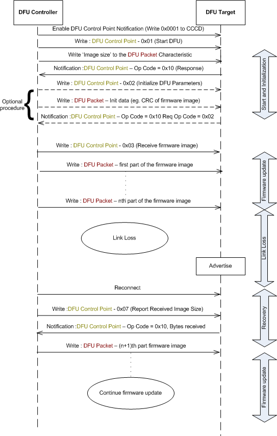
In case no connection is established with the DFU Target after 60 seconds, Target device will restart in normal mode with old firmware, in case there was an existing application, else in DFU mode, in case there was no application on the device.
When the Nordic bootloader application detects that the connection has been idle for a time period, meaning that the DFU Controller has not written any packet that will result in the progress of the firmware update, the update will be stopped, the connection will be terminated, and the previously valid application will be started. If no valid application exists in the flash, the application stays in bootloader mode waiting for a reconnection from the DFU Controller.
When the Nordic bootloader application detects a link loss, DFU state and image size is remembered. On reconnection to the Controller, the transfer can resume from where it had stopped. Controller can request size of received image using the Report Received Image Size Procedure and start transfer by applying the necessary offset. Idle Mode Procedures apply in the disconnected state on link loss.
This feature allows the DFU Controller to subscribe for a notification from the DFU Target, each time a given number of firmware packets is received by the latter. To use this feature, the DFU Controller should write to the DFU Control Point, the Op Code 0x08 - Packet Receipt Notification Request followed by the Number of packets. If the Number of packets field is set to N, then the DFU Target will send a Notification of the DFU Control Point with Op Code = 0x11 - Packet Receipt Notification, each time it receives N number of firmware packets. The DFU Controller should wait for this notification each time it has finished sending N number of firmware packets.
In Packet Receipt Notification, the DFU Target also sends the number of bytes of firmware data received until that point of time. This may be used for any consistency checks by the DFU Controller.
This section describes the security considerations for a DFU Target and DFU Controller.
All supported characteristics specified by the DFU Service are set to Security Mode 1 and Security Level 1.

