nRF Machine Learning
The nRF Machine Learning application is an out of the box reference design of an embedded machine learning using Edge Impulse. The application gathers data from sensors, forwards data to the Edge Impulse platform, and runs the machine learning model. It also displays results of the machine learning model on LEDs. The Edge Impulse platform collects data from sensors, trains machine learning model, and deploys the model to your Nordic Semiconductor’s device. To learn more about Edge Impulse support in the nRF Connect SDK see Using Edge Impulse with the nRF Connect SDK.
Overview
To perform its tasks, the nRF Machine Learning application uses components available in Zephyr and the nRF Connect SDK, namely the Common Application Framework modules and Sensors for sampling sensors, and UART or Nordic UART Service (NUS) for forwarding data. It also uses the Edge Impulse’s data forwarder protocol.
Sampling sensors
The application handles the sensor sampling using the CAF: Sensor sampler module. This module uses Zephyr’s Sensors to handle the sampling. This approach allows to use any sensor available in Zephyr.
By default, the following sensors are used by the application:
Thingy:52 - built-in accelerometer (
LIS2DH).Thingy:53 - built-in accelerometer (
ADXL362).nRF52840 Development Kit - simulated sensor (
sensor_simavailable in the nRF Connect SDK). The simulated sensor generates predefined waves as acceleration. This development kit does not have a built-in accelerometer.
Forwarding data
The application uses Edge Impulse’s data forwarder protocol to forward data to Edge Impulse studio. By default, the following transports are used:
Thingy:52 uses Nordic UART Service (NUS).
Thingy:53 uses Nordic UART Service (NUS).
nRF52840 Development Kit uses UART.
Machine learning model
The application handles the machine learning model using the Edge Impulse wrapper library available in the nRF Connect SDK. The model performs the classification task by assigning a label to input data. The labels that are assigned by the machine learning model are specific to the given model.
By default, the application uses pretrained machine leaning models deployed in Edge Impulse studio:
Both Thingy:52 and Thingy:53 share the same machine learning model. The model uses the data from the built-in accelerometer to recognize the following gestures:
idle- the device is placed on a flat surface.updown- the device is moved in updown direction.rotate- the device is rotated.tap- the device is tapped while placed on a flat surface.
Unknown gestures, such as shaking the device, are recognized as anomaly.
On the nRF52840 Development Kit, the model uses simulated sensor data to recognize the following simulated wave types:
sinetriangleidle
The
squarewave signal can also be generated by the simulated sensor. This signal is unknown to the machine learning model and therefore it is marked as anomaly.
The application displays LED effects that correspond to the machine learning results. For more detailed information, see the User interface section.
Firmware architecture
The nRF Machine Learning application has a modular structure, where each module has a defined scope of responsibility. The application uses the Event Manager to distribute events between modules in the system.
The following figure shows the application architecture. The figure visualizes relations between Event Manager, modules, drivers, and libraries.

nRF Machine Learning application architecture
Since the application architecture is uniform and the code is shared, the set of modules in use depends on configuration. In other words, not all of the modules need to be enabled for a given reference design. For example, the CAF: Bluetooth LE state module and CAF: Bluetooth LE advertising module modules are not enabled if the configuration does not use Bluetooth®.
See Application internal modules for detailed information about every module used by the nRF Machine Learning application.
User interface
The application supports a simple user interface. You can control the application using predefined buttons, while LEDs are used to display information.
Buttons
The application supports a button that is used to switch between data forwarding and running the machine learning model. You can trigger the change by pressing and holding the button for longer than 5 seconds.
If the application uses the simulated sensor signal, you can use another button to change signal generated by the simulated sensor. The change is triggered by any press of the button.
By default, the following buttons are used by the application:
Thingy:52:
The SW2 button switches between data forwarding and running the machine learning model.
Thingy:53:
The SW3 button switches between data forwarding and running the machine learning model.
nRF52840 Development Kit:
Button 1 switches between data forwarding and running a machine learning model.
Button 3 changes the signal generated by the simulated sensor.
LEDs
The application uses one LED to display the application state. The LED displays either the state of data forwarding or the machine learning prediction results. You can configure the LED effect in the application configuration files.
If the application uses the simulated sensor signal, it uses another LED to display the effect that represents the signal generated by the simulated sensor. The application defines common LED effects for both the machine learning results and the simulated sensor signal.
By default, the application uses the following LED effects:
Thingy:52 and Thingy:53 display the application state in the RGB scale. Thingy:52 uses the Lightwell LEDs and Thingy:53 uses the LED1.
If the device is returning the machine learning prediction results, the LED uses following predefined colors:
rotate- redupdown- greentap- blueAnomaly - purple
If the machine learning model is running, but it has not detected anything yet or the
idlestate is detected, the LED is blinking. After a successful detection, the LED is set to the predefined color. The LED effect is overridden on the next successful detection.If the device forwards data, the LED color turns red and uses the following blinking patterns:
LED blinks slowly if it is not connected.
LED blinks with an average frequency if it is connected, but is not actively forwarding data.
LED blinks rapidly if it is connected and is actively forwarding data.
On the nRF52840 Development Kit, the LED1 displays the application state and the LED2 displays the signal generated by the simulated sensor.
If the device is returning the machine learning prediction results, the LED1 blinks for a predefined number of times and then turns off for a period of time. Then the sequence is repeated. The machine learning result is represented by the number of blinks:
sine- 1 blinktriangle- 2 blinkssquare- 3 blinksidle- 4 blinks
If the machine learning model is running, but it has not detected anything yet or it has detected an anomaly, the LED1 is breathing.
If the device forwards data, the LED1 uses the following blinking patterns:
LED blinks slowly if it is not connected.
LED blinks with an average frequency if it is connected, but is not actively forwarding data.
LED blinks rapidly if it is connected and is actively forwarding data.
Requirements
The application supports the following development kits:
Hardware platforms |
PCA |
Board name |
Build target |
|---|---|---|---|
Thingy:52 |
PCA20020 |
|
|
Thingy:53 |
PCA20053 |
|
|
PCA10056 |
|
The available configurations use only built-in sensors or the simulated sensor signal. There is no need to connect any additional components to the board.
Programming Thingy:52
The Thingy:52 does not have the J-Link debug IC and the application configuration does not use a bootloader. Use an external debugger to program the firmware. See Thingy:52 documentation for details.
Programming Thingy:53
If you build this application for Thingy:53, it enables additional features. See Thingy:53 application guide for details.
Custom model requirements
The default application configurations rely on pretrained machine learning models that can be automatically downloaded during the application build. If you want to train and deploy a custom machine learning model using Edge Impulse Studio, you need a user account for the Edge Impulse Studio web-based tool. The user account is not needed to perform predictions using the pretrained models.
Data forwarding requirements
To forward the collected data using Edge Impulse’s data forwarder, you must install the Edge Impulse CLI. See Edge Impulse CLI installation guide for instructions.
Nordic UART Service requirements
If you want to forward data over Nordic UART Service (NUS), you need an additional development kit that is able to run the Bluetooth: Central UART sample. Check the sample Requirements section for the list of supported development kits. The sample is used to receive data over NUS and forward it to the host computer over UART. See Testing with Thingy devices for how to test this solution.
nRF Machine Learning build types
The nRF Machine Learning application does not use a single prj.conf file.
Configuration files are provided for different build types for each supported board.
Build types enable you to use different sets of configuration options for each board.
You can create several build type .conf files per board and select one of them when building the application.
This means that you do not have to use one prj.conf file for your project and modify it each time to fit your needs.
Before you start testing the application, you can select one of the build types supported by nRF Machine Learning application, depending on your development kit and the building method. The application supports the following build types:
ZDebug– Debug version of the application - can be used to verify if the application works correctly.ZRelease– Release version of the application - can be used to achieve better performance and reduce memory consumption.
The given board can also support some additional configurations of the nRF Machine Learning application.
For example, the nRF52840 Development Kit supports ZDebugNUS configuration that uses Nordic UART Service (NUS) instead of UART for data forwarding.
Note
Selecting a build type is optional.
The ZDebug build type is used by default if no build type is explicitly selected.
Configuration
The nRF Machine Learning application is modular and event-driven. You can enable and configure the modules separately for selected board and build type. See the documentation page of selected module for information about functionalities provided by the module and its configuration. See Application internal modules for list of modules available in the application.
Configuration files
The nRF Machine Learning application uses the following files as configuration sources:
Devicetree Specification (DTS) files - These reflect the hardware configuration. See Devicetree Guide for more information about the DTS data structure.
Kconfig files - These reflect the software configuration. See Kconfig - Tips and Best Practices for information about how to configure them.
_deffiles - These contain configuration arrays for the application modules. The_deffiles are used by the nRF Machine Learning application modules and Common Application Framework modules.
The application configuration files for a given board must be defined in a board-specific directory in the applications/machine_learning/configuration/ directory.
For example, the configuration files for the Thingy:52 are defined in the applications/machine_learning/configuration/thingy52_nrf52832 directory.
The following configuration files can be defined for any supported board:
app_build_type.conf- Kconfig configuration file for a build type. To support a given build type for the selected board, you must define the configuration file with a proper name. For example, theapp_ZDebug.confdefines configuration forZDebugbuild type.dts.overlay- DTS overlay file specific for the board. Defining the DTS overlay file for a given board is optional._deffiles - These files are defined separately for modules used by the application. You must define a_deffile for every module that requires it and enable it in the configuration for the given board. The_deffiles that are common for all the boards and build types are located in theapplications/machine_learning/configuration/commondirectory.
Multi-image builds
The Thingy:53 uses multi-image build with the following child images:
MCUboot bootloader
Bluetooth HCI RPMsg
See Multi-image builds for detailed information about multi-image builds and child image configuration.
Building and running
The nRF machine learning application is built the same way to any other nRF Connect SDK application or sample. Building the default configurations requires an Internet connection, because the machine learning model source files are downloaded from web during the application build.
This sample can be found under applications/machine_learning in the nRF Connect SDK folder structure.
See Building and programming an application for information about how to build and program the application.
Selecting a build type
Before you start testing the application, you can select one of the nRF Machine Learning build types, depending on your development kit and building method.
Selecting a build type in SES
To select the build type in SEGGER Embedded Studio:
Go to File > Open nRF Connect SDK project, select the current project, and specify the board name and build directory.
Select Extended Settings.
In the Extra CMake Build Options field, specify
-DCMAKE_BUILD_TYPE=selected_build_type. For example, forZReleaseset the following value:-DCMAKE_BUILD_TYPE=ZRelease.Do not select Clean Build Directory.
Click OK to re-open the project.
Note
You can also specify the build type in the Additional CMake Options field in Tools > Options > nRF Connect. However, the changes will only be applied after re-opening the project. Reloading the project is not sufficient.
Selecting a build type from command line
To select the build type when building the application from command line, specify the build type by adding the following parameter to the west build command:
-- -DCMAKE_BUILD_TYPE=selected_build_type
For example, you can replace the selected_build_type variable to build the ZRelease firmware for PCA20041 by running the following command in the project directory:
west build -b nrf52840dk_nrf52840 -d build_nrf52840dk_nrf52840 -- -DCMAKE_BUILD_TYPE=ZRelease
The build_nrf52840dk_nrf52840 parameter specifies the output directory for the build files.
Note
If the selected board does not support the selected build type, the build is interrupted.
For example, if the ZDebugNUS build type is not supported by the selected board, the following notification appears:
Configuration file for build type ZDebugNUS is missing.
Providing API key
If the URI of the Edge Impulse zip file requires providing an additional API key, you can provide it using the following CMake definition: EI_API_KEY_HEADER.
This definition is set in a similar way as selected build type.
For more detailed information about building the machine learning model in the nRF Connect SDK, see Using Edge Impulse with the nRF Connect SDK.
Tip
The nRF Machine Learning application configurations available in the nRF Connect SDK do not require providing an API key to download the model. The model is download from web, but no authentication is required.
Testing
After programming the application to your development kit, you can test the nRF Machine Learning application. You can test running the machine learning model on an embedded device and forwarding data to Edge Impulse studio. The detailed test steps for the nRF52840 Development Kit, the Thingy:52, and the Thingy:53 are described in the following subsections.
Application logs
In most of the provided debug configurations, the application provides logs through the RTT. See Connecting via RTT for detailed instructions about accessing the logs.
Note
The Thingy:53 in the ZDebug configuration provides logs through the USB CDC ACM serial.
See Working with Thingy:53 for detailed information about working with the Thingy:53.
You can also use ZDebugRTT configuration to have the Thingy:53 use RTT for logs.
Testing with Thingy devices
After programming the application, perform the following steps to test the nRF Machine Learning application on the Thingy:
Turn on the Thingy. The application starts in a mode that runs the machine learning model. The RGB LED is blinking, because no gesture has been recognized by the machine learning model yet.
Tap the device. The
tapgesture is recognized by the machine learning model. The LED color changes to blue and the LED stays turned on.Move the device up and down. The
updowngesture is recognized by the machine learning model. The LED color changes to green and the LED stays turned on.Rotate the device. The
rotategesture is recognized by the machine learning model. The LED color changes to red and the LED stays turned on.Shake the device. The machine learning model detects an anomaly. The LED color changes to purple and the LED stays turned on.
Press and hold the button for more than 5 seconds to switch to the data forwarding mode. After the mode is switched, the LED color changes to red and the LED starts blinking very slowly.
Program the Bluetooth: Central UART sample to a compatible development kit, for example the nRF52840 Development Kit.
Turn on the programmed device. After a brief delay the Bluetooth® connection between the sample and the Thingy is established. The Thingy forwards the sensor readouts over NUS. The LED on the Thingy starts to blink rapidly.
Connect to the Bluetooth® Central UART sample with a terminal emulator (for example, PuTTY). See How to connect with PuTTY for the required settings.
Observe the sensor readouts represented as comma-separated values. Every line represents a single sensor readout. The Thingy forwards sensor readouts over NUS to the Central UART sample. The sample forwards the data to the host over UART.
Turn off PuTTY to ensure that only one program has access to data on UART.
Optionally, you can also connect to the device using Edge Impulse’s data forwarder and forward data to Edge Impulse studio (after logging in). See Forwarding data to Edge Impulse studio for details.
Testing with the nRF52840 DK
After programming the application, perform the following steps to test the nRF Machine Learning application on the nRF52840 Development Kit:
Turn on the development kit. The application starts in a mode that runs the machine learning model. Initially, LED2 displays the LED effect representing
sinewave (1 blink) and LED1 is breathing, because the signal was not yet recognized by the machine learning model. After a brief delay, the machine learning model recognizes the simulated signal. LED1 and LED2 display the same LED effect.Press Button 3 to change the generated acceleration signal. Right after the signal change, effects displayed by LEDs are different. After a brief delay, the machine learning model recognizes the
trianglewave and the same effect (2 blinks) is displayed by both LEDs.Press Button 3 to again change generated acceleration signal. The
squarewave (3 blinks) is displayed only by the LED2. This signal is marked as anomaly by the machine learning model and LED1 starts breathing.Press and hold Button 1 for more than 5 seconds to switch to the data forwarding mode. After the mode is switched, LED1 starts to blink rapidly.
Connect to the development kit with a terminal emulator (for example, PuTTY). See How to connect with PuTTY for the required settings.
Observe the sensor readouts represented as comma-separated values. Every line represents a single sensor readout.
Turn off PuTTY to ensure that only one program will access data on UART.
Optionally, you can also connect to the device using Edge Impulse’s data forwarder and forward data to Edge Impulse studio (after logging in). See Forwarding data to Edge Impulse studio for details.
Forwarding data to Edge Impulse studio
To start forwarding data to Edge Impulse studio:
Make sure you meet the Data forwarding requirements before forwarding data to Edge Impulse studio.
Run the
edge-impulse-data-forwarderEdge Impulse command line tool.Log in to Edge Impulse studio and perform the following steps:
Go to the Data acquisition tab.
In the Record new data panel, set the desired values and click Start sampling.
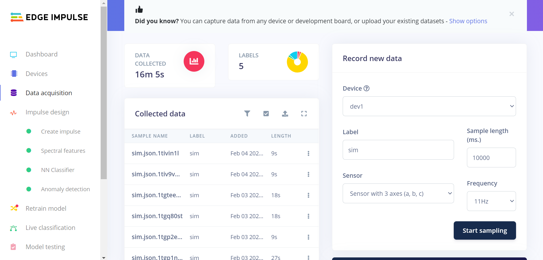
Sampling under Data acquisition in Edge Impulse studio
Observe the received sample data on the raw data graph under the panel. The observed signal depends on the acceleration readouts.
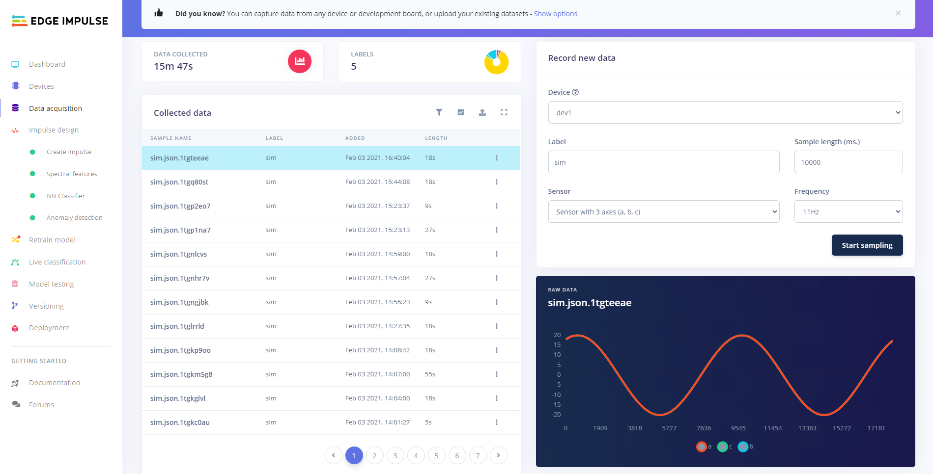
Sampling example
Porting guide
You can port the nRF Machine Learning application to any board available in the nRF Connect SDK or Zephyr.
To do so, create the board-specific directory in applications/machine_learning/configuration/ and add the application configuration files there.
See the Configuration for detailed information about the nRF Machine Learning application configuration.
Dependencies
The application uses the following Zephyr drivers and libraries:
The application uses the following nRF Connect SDK libraries and drivers:
In addition, you can use the Bluetooth: Central UART sample together with the application. The sample is used to receive data over NUS and forward it to the host over UART.
Application internal modules
The nRF Machine Learning application uses modules available in Common Application Framework (CAF), a set of generic modules based on Event Manager and available to all applications and a set of dedicated internal modules. See Firmware architecture for more information.
The nRF Machine Learning application uses the following modules available in CAF:
See the module pages for more information about the modules and their configuration.
The nRF Machine Learning application also uses the following dedicated application modules:
ei_data_forwarder_bt_nusThe module forwards the sensor readouts over NUS to the connected Bluetooth Central. The sensor data is forwarded only if the connection is secured and connection interval is within the limit defined by
CONFIG_BT_PERIPHERAL_PREF_MAX_INTandCONFIG_BT_PERIPHERAL_PREF_MAX_INT.ei_data_forwarder_uartThe module forwards the sensor readouts over UART.
led_stateThe module displays the application state using LEDs. The LED effects used to display the state of data forwarding, the machine learning results, and the state of the simulated signal are defined in
led_state_def.hfile located in the application configuration directory. The common LED effects are used to represent the machine learning results and the simulated sensor signal.ml_runnerThe module uses Edge Impulse wrapper API to control running the machine learning model. It provides the prediction results using
ml_result_event. The module runs the machine learning model and provides results only if there is an active subsriber. An application module can inform that it is actively listening for results usingml_result_signin_event.ml_stateThe module controls switching between running the machine learning model and forwarding the data. The change is triggered by a long press of the button defined in the module’s configuration.
sensor_sim_ctrlThe module controls parameters of the generated simulated sensor signal. It switches between predefined sets of parameters for the simulated signal. The parameters of the generated signals are defined by the
sensor_sim_ctrl_def.hfile located in the application configuration directory.
Note
The ei_data_forwarder_bt_nus and ei_data_forwarder_uart modules stop forwarding the sensor readouts if they receive a sensor_event that cannot be forwarded and needs to be dropped.
This could happen, for example, if the selected sensor sampling frequency is too high for the used implementation of the Edge Impulse data forwarder.
Data forwarding is stopped to make sure that dropping samples is noticed by the user.
If you switch to running the machine learning model and then switch back to data forwarding, the data will be again forwarded to the host.