nRF Machine Learning: Application description
The nRF Machine Learning application gathers data from sensors, forwards data to the Edge Impulse platform, and runs the machine learning model. It also displays the results of the machine learning model on LEDs. The Edge Impulse platform collects data from sensors, trains the machine learning model, and deploys the model to your Nordic Semiconductor’s device. To learn more about Edge Impulse support in the nRF Connect SDK see Edge Impulse integration.
Application overview
To perform its tasks, the nRF Machine Learning application uses components available in Zephyr and the nRF Connect SDK, namely the Common Application Framework modules and Sensors for sampling sensors, and Universal Asynchronous Receiver-Transmitter (UART) or Nordic UART Service (NUS) for forwarding data. It also uses the Edge Impulse’s data forwarder protocol.
Sampling sensors
The application handles the sensor sampling using the CAF: Sensor manager module. This module uses Zephyr’s Sensors to handle the sampling. This approach allows you to use any sensor available in Zephyr.
By default, the following sensors are used by the application:
Thingy:53 - Built-in accelerometer (
ADXL362).nRF52840 Development Kit (DK) - Simulated sensor (Simulated sensor driver). The simulated sensor generates predefined waves as acceleration. This development kit does not have a built-in accelerometer.
nRF5340 DK - Simulated sensor (Simulated sensor driver). The simulated sensor generates predefined waves as acceleration. This development kit does not have a built-in accelerometer.
nRF54L15 DK - Simulated sensor (Simulated sensor driver). The simulated sensor generates predefined waves as acceleration. This development kit does not have a built-in accelerometer.
nRF54H20 DK - The development kit does not have a built-in accelerometer. However, it supports the following configurations:
Single-core - Accelerometer (
ADXL362) connected to the DK with the PCA63566 shield. See the shield documentation under thenrf/boards/shields/pca63566/doc/index.rstpath.Dual-core - Accelerometer (
ADXL362) connected to the DK with the PCA63566 shield. Sensor is sampled from Peripheral Processor (PPR). See the shield documentation under thenrf/boards/shields/pca63566/doc/index.rstpath.
Forwarding data
The application uses Edge Impulse’s data forwarder protocol to forward data to Edge Impulse studio. By default, the following transports are used:
Thingy:53 uses Nordic UART Service (NUS).
The nRF52840 DK uses Universal Asynchronous Receiver-Transmitter (UART).
The nRF5340 DK uses Universal Asynchronous Receiver-Transmitter (UART).
The nRF54L15 DK uses Universal Asynchronous Receiver-Transmitter (UART).
The nRF54H20 DK uses Nordic UART Service (NUS).
Machine learning model
The application handles the machine learning model using the Edge Impulse wrapper library available in the nRF Connect SDK. The model performs the classification task by assigning a label to the input data. The labels that are assigned by the machine learning model are specific to the given model.
By default, the application uses pre-trained machine learning models deployed in Edge Impulse studio:
Thingy:53 uses the nRF Connect SDK hardware accelerometer machine learning model. The model uses the data from the built-in accelerometer to recognize the following gestures:
idle- The device is placed on a flat surface.updown- The device is moved in up-down direction.rotate- The device is rotated.tap- The device is tapped while placed on a flat surface.
Unknown gestures, such as shaking the device, are recognized as anomalies.
The nRF52840, nRF5340 and nRF54L15 DKs use the nRF Connect SDK simulated sensor machine learning model. The model uses simulated sensor data to recognize the following simulated wave types:
sinetriangleidle
The
squarewave signal can also be generated by the simulated sensor. This signal is unknown to the machine learning model, and therefore, it is marked as an anomaly.
The application displays LED effects that correspond to the machine learning results. For more detailed information, see the User interface section.
Power management
Reducing power consumption is important for all battery-powered devices.
In the nRF Machine Learning application, application modules are automatically suspended or turned off if the device is not in use for a predefined period.
The application uses CAF: Power manager module for this purpose.
This means that Zephyr power management is forced to the PM_STATE_ACTIVE state when the device is in either the power management active or the power management suspended state, but the power off state is forced directly by CAF: Power manager module as Zephyr’s PM_STATE_SOFT_OFF state.
In the
POWER_MANAGER_LEVEL_ALIVEstate, the device is in working condition, Bluetooth® is advertising whenever required and all the connections are maintained.In the
POWER_MANAGER_LEVEL_SUSPENDEDstate, the device maintains the active Bluetooth connection.In the
POWER_MANAGER_LEVEL_OFFstate, the CPU is switched to the off mode.
In the suspended and OFF states, most of the functionalities are disabled. For example, LEDs and sensors are turned off, and Bluetooth advertising is stopped.
Any button press can wake up the device.
For the Thingy:53, the sensor supports a trigger that can be used for active power management.
As long as the device detects acceleration, the board is kept in the active state.
When the board is in the POWER_MANAGER_LEVEL_SUSPENDED state, it can be woken up by acceleration threshold by moving the device.
You can define the time interval after which the peripherals are suspended or powered off using the CONFIG_CAF_POWER_MANAGER_TIMEOUT Kconfig option.
By default, this period is set to 120 seconds.
Firmware architecture
The nRF Machine Learning application has a modular structure, where each module has a defined scope of responsibility. The application uses the Application Event Manager to distribute events between modules in the system.
The following figure shows the application architecture. The figure visualizes relations between Application Event Manager, modules, drivers, and libraries.

nRF Machine Learning application architecture
Since the application architecture is uniform and the code is shared, the set of modules in use depends on configuration. In other words, all modules do not need to be enabled for a given reference design. For example, the CAF: Bluetooth LE state module and CAF: Bluetooth LE advertising module modules are not enabled if the configuration does not use Bluetooth.
See nRF Machine Learning: Internal modules for detailed information about every module used by the nRF Machine Learning application.
Firmware architecture for nRF54H20 DK
On the nRF54H20 DK, the architecture of the nRF Machine Learning application is split in two, as part of the application is running on a separate Peripheral Processor (PPR). PPR handles sensor sampling and sending of data to the application processor.
The following figure shows the application architecture for the nRF54H20 DK, visualizing the relations between the Application Event Manager, modules, drivers, and libraries.

Architecture of the nRF Machine Learning application for the nRF54H20 DK
Programming Thingy:53
If you build this application for Thingy:53, it enables additional features. See Application guide for Thingy:53 for details.
Programming nRF5340 DK
If you build this application for the nRF5340 DK, it enables additional features similar to the ones that are enabled for Thingy:53:
MCUboot bootloader with serial recovery and multi-image update.
Static configuration of Partition Manager.
DFU over-the-air using Simple Management Protocol (SMP) over Bluetooth.
See Developing with nRF53 Series for detailed information about these features.
The nRF5340 DK has a J-Link debug IC that you can use to program the firmware. Alternatively, you can update the firmware over MCUboot serial recovery or DFU over-the-air using the Simple Management Protocol over Bluetooth. If you use the bootloader to update the firmware, the new firmware must be compatible with the used bootloader and partition map.
The nRF5340 DK uses RTT as the logger’s backend. The RTT logs can be easily accessed, because the DK has a built-in SEGGER chip.
Custom model requirements
The default application configurations rely on pre-trained machine learning models that can be automatically downloaded during the application build. If you want to train and deploy a custom machine learning model using Edge Impulse Studio, you need a user account for the Edge Impulse Studio web-based tool. You do not need a user account to perform predictions using the pre-trained models.
Data forwarding requirements
To forward the collected data using Edge Impulse’s data forwarder, you must install the Edge Impulse CLI. See the Edge Impulse CLI installation guide for instructions.
Nordic UART Service requirements
If you want to forward data over Nordic UART Service (NUS), you need an additional development kit that is able to run the Bluetooth: Central UART sample. Check the Requirements section of the sample for the list of supported development kits. The sample is used to receive data over NUS and forward it to the host computer over UART. See Testing with Thingy:53 for how to test this solution.
Requirements
The application supports the following development kits:
Hardware platforms |
PCA |
Board name |
Board target |
Shields |
|---|---|---|---|---|
PCA20053 |
|
|||
PCA10175 |
|
|
||
PCA10095 |
|
|||
PCA10056 |
|
The available configurations use only built-in sensors or the simulated sensor signal. You do not need to connect any additional components to the board.
When built for a board target with the */ns variant, the sample is configured to compile and run as a non-secure application with Cortex-M Security Extensions enabled.
Therefore, it automatically includes Trusted Firmware-M that prepares the required peripherals and secure services to be available for the application.
User interface
The application supports a simple user interface. You can control the application using predefined buttons, while LEDs are used to display information.
LEDs
The application uses one LED to display the application state. The LED displays either the state of data forwarding or the machine learning prediction results. You can configure the LED effect in the application configuration files.
If the application uses the simulated sensor signal, it uses another LED to display the effect that represents the signal generated by the simulated sensor. The application defines common LED effects for both the machine learning results and the simulated sensor signal.
By default, the application uses the following LED effects:
Thingy:53 displays the application state in the RGB scale using LED1.
If the device is returning the machine learning prediction results, the LED uses the following predefined colors:
rotate- Redupdown- Greentap- BlueAnomaly - Purple
If the machine learning model is running but has not detected anything yet or the
idlestate is detected, the LED is blinking. After a successful detection, the LED is set to the predefined color. The LED effect is overridden on the next successful detection.If the device forwards data, the LED color turns red and uses the following blinking patterns:
Blinks slowly if it is not connected.
Blinks with an average frequency if it is connected but is not actively forwarding data.
Blinks rapidly if it is connected and is actively forwarding data.
Both nRF5340 DK and nRF52840 DK use monochromatic LEDs to display the application state. The LED1 displays the application state and the LED2 displays the signal generated by the simulated sensor.
If the device is returning the machine learning prediction results, the LED1 blinks for a predefined number of times and then turns off for a period of time. Then the sequence is repeated. The machine learning result is represented by the number of blinks:
sine- one blinktriangle- two blinkssquare- three blinksidle- four blinks
If the machine learning model is running but has not detected anything yet or has detected an anomaly, the LED1 is breathing.
If the device forwards data, the LED1 has the following blinking patterns:
Blinks slowly if it is not connected.
Blinks with an average frequency if it is connected but is not actively forwarding data.
Blinks rapidly if it is connected and is actively forwarding data.
The nRF54L15 DK uses monochromatic LEDs to display the application state. The LED1 displays the application state and the LED3 displays the signal generated by the simulated sensor.
If the device is returning the machine learning prediction results, the LED1 blinks for a predefined number of times and then turns off for a period of time. Then the sequence is repeated. The machine learning result is represented by the number of blinks:
sine- one blinktriangle- two blinkssquare- three blinksidle- four blinks
If the machine learning model is running but has not detected anything yet or has detected an anomaly, the LED1 is breathing.
If the device forwards data, the LED1 has the following blinking patterns:
Blinks slowly if it is not connected.
Blinks with an average frequency if it is connected but is not actively forwarding data.
Blinks rapidly if it is connected and is actively forwarding data.
nRF54H20 DK uses monochromatic LEDs to display the application state. LED0, LED1 and LED2 display the application state.
If the device is returning the machine learning prediction results, a pattern of LEDs are turn on. The machine learning result is represented by:
LED0 -
updownLED1 -
rotateLED2 -
tapLED2 and LED3 - Anomaly
If the machine learning model is running, but it has not detected anything yet or the
idlestate is detected, LED0, LED1, and LED2, keep blinking.If the device forwards data, LED0, LED1 and LED2 has the following blinking patterns:
Blinks slowly if it is not connected.
Blinks with an average frequency if it is connected, but is not actively forwarding data.
Blinks rapidly if it is connected and is actively forwarding data.
Configuration
See Configuring and building for information about how to permanently or temporarily change the configuration.
Configuration files
The nRF Machine Learning application uses the following files as configuration sources:
Devicetree Specification (DTS) files - These reflect the hardware configuration. See Devicetree Guide for more information about the DTS data structure.
Kconfig files - These reflect the software configuration. See Kconfig - Tips and Best Practices for information about how to configure them.
_deffiles - These contain configuration arrays for the application modules. The_deffiles are used by the nRF Machine Learning application modules and Common Application Framework modules.
The application configuration files for a given board must be defined in a board-specific directory in the applications/machine_learning/configuration/ directory.
For example, the configuration files for the Thingy:53 are defined in the applications/machine_learning/configuration/thingy53_nrf5340_cpuapp directory.
The following configuration files can be defined for any supported board:
prj_<build_type>.conf- Kconfig configuration file for a custom build type. To support a given build type for the selected board, you must define the configuration file with a proper name. See nRF Machine Learning build types for more information.app.overlay- DTS overlay file specific for the board. Defining the DTS overlay file for a given board is optional._deffiles - These files are defined separately for modules used by the application. You must define a_deffile for every module that requires it and enable it in the configuration for the given board. The_deffiles that are common for all the boards and build types are located in theapplications/machine_learning/configuration/commondirectory.
The nRF Machine Learning application introduces application-specific Kconfig options that you can use to simplify the application configuration. For more information, see the nRF Machine Learning: Application-specific Kconfig options page.
Multi-image builds
The Thingy:53 and the nRF5340 DK use multi-image build with the following child images:
MCUboot bootloader
Bluetooth HCI RPMsg
You can define the application-specific configuration for the mentioned child images in the board-specific directory in the applications/machine_learning/configuration/ directory.
The Kconfig configuration file should be located in subdirectory child_image/<child_image_name> and its name should match the application Kconfig file name, and it should contain the build type if necessary.
For example, the applications/machine_learning/configuration/thingy53_nrf5340_cpuapp/child_image/hci_ipc/prj.conf file defines configuration of Bluetooth HCI RPMsg for the debug build type on thingy53_nrf5340_cpuapp board, while the applications/machine_learning/configuration/thingy53_nrf5340_cpuapp/child_image/hci_ipc/prj_release.conf file defines configuration of Bluetooth HCI RPMsg for the release build type.
See Multi-image builds using child and parent images for detailed information about multi-image builds and child image configuration.
nRF Machine Learning build types
The nRF Machine Learning application does not use a single prj.conf file.
Before you start testing the application, you can select one of the build types supported by the application.
Not every board supports both mentioned build types.
See Custom build types and Providing CMake options for more information.
The application supports the following build types:
Build type |
File name |
Supported board target |
Description |
|---|---|---|---|
Debug (default) |
|
All from Requirements |
Debug version of the application; can be used to verify if the application works correctly. |
Release |
|
|
Release version of the application; can be used to achieve better performance and reduce memory consumption. |
NUS |
|
|
Debug version of the application that uses Nordic UART Service (NUS) instead of Universal Asynchronous Receiver-Transmitter (UART) for data forwarding. |
RTT |
|
|
Debug version of the application that uses RTT for printing logs instead of USB CDC. |
Single-core |
|
|
Configuration that does not use Peripheral Processor (PPR) for data sampling. Data is collected with the application CPU instead. |
Building and running
The nRF Machine Learning application is built the same way as any other nRF Connect SDK application or sample. Building the default configurations requires an Internet connection, because the machine learning model source files are downloaded from the web during the application build.
This application can be found under applications/machine_learning in the nRF Connect SDK folder structure.
To build the application, follow the instructions in Building an application for your preferred building environment. See also Programming an application for programming steps and Testing and optimization for general information about testing and debugging in the nRF Connect SDK.
Note
When building repository applications in the SDK repositories, building with sysbuild is enabled by default.
If you work with out-of-tree freestanding applications, you need to manually pass the --sysbuild parameter to every build command or configure west to always use it.
nRF54H20 DK
Note
This application does not work in the default configuration for the nRF54H20 DK without additional parameters like shields or snippets.
When using the nRF54H20 DK Engineering B (from v0.8.0 to 0.8.2), you must build samples and applications using the board revision 0.8.0 with the
<board>@<revision>syntax. For example,nrf54h20dk@0.8.0/nrf54h20/cpuappwhen building for the application core, ornrf54h20dk@0.8.0/nrf54h20/cpuradwhen building for the radio core.To build the application for the nRF54H20 DK with the sensor sampling done by the Application core (single-core application), run the following command:
west build -b nrf54h20dk/nrf54h20/cpuapp -- -Dmachine_learning_SHIELD=pca63566 -DFILE_SUFFIX="singlecore"or use twister test case:
west build -b nrf54h20dk/nrf54h20/cpuapp -T applications.machine_learning.sensor_hub.zdebug.singlecore .To build the application for the nRF54H20 DK with the sensor sampling on the PPR core (dual-core application), run the following command:
west build -b nrf54h20dk/nrf54h20/cpuapp -- -DSB_CONFIG_ML_APP_INCLUDE_REMOTE_IMAGE=y -Dmachine_learning_SNIPPET=nordic-ppr -Dmachine_learning_SHIELD=pca63566_fwd -Dremote_SHIELD=pca63566or use twister test case:
west build -b nrf54h20dk/nrf54h20/cpuapp -T applications.machine_learning.sensor_hub.zdebug .Note
Programming the nRF54H20 SoC can sometimes fail due to conflicts in the resource configuration. This can happen if, for example, an application programmed to the nRF54H20 SoC configured the UICRs for one or more cores in a way that is incompatible with the configuration required by the application you are trying to program on the SoC.
To fix this error and erase the UICR for the application core, run the following command:
nrfutil device recover --core ApplicationIf your sample also uses the radio core, you must also erase the UICRs for the radio core. To erase the UICR for the radio core, run the following command:
nrfutil device recover --core NetworkFor more information on the command, run:
nrfutil device recover --helpYou can then run
west flashto program your application.
Selecting a build type
Before you start testing the application, you can select one of the nRF Machine Learning build types. See Providing CMake options for information about how to select a build type.
Providing API key
If the URI of the Edge Impulse .zip file requires providing an additional API key, you can provide it using the EI_API_KEY_HEADER CMake definition.
This definition is set in a similar way as selecting a build type.
For more detailed information about building the machine learning model in the nRF Connect SDK, see Edge Impulse integration.
Tip
The nRF Machine Learning application configurations available in the nRF Connect SDK do not require providing an API key to download the model. The model is downloaded from the web, but no authentication is required.
Testing
After programming the application to your development kit, you can test the nRF Machine Learning application. You can test running the machine learning model on an embedded device and forwarding data to Edge Impulse studio. The detailed test steps for the DKs and the Thingy:53 are described in the following subsections.
Application logs
In most of the provided debug configurations, the application provides logs through the RTT.
See Testing and optimization for detailed instructions about accessing the logs.
Note
The Thingy:53 in the debug configuration provides logs through the USB CDC ACM serial.
See Developing with nRF53 Series for detailed information about working with the Thingy:53.
You can also use the rtt configuration to have the Thingy:53 use RTT for logs.
Testing with Thingy:53
After programming the application, perform the following steps to test the nRF Machine Learning application on the Thingy:
Turn on the Thingy. The application starts in a mode that runs the machine learning model. The RGB LED is blinking, because no gesture has been recognized by the machine learning model yet.
Tap the device. The
tapgesture is recognized by the machine learning model. The LED color changes to blue, and the LED stays turned on.Move the device up and down. The
updowngesture is recognized by the machine learning model. The LED color changes to green, and the LED stays turned on.Rotate the device. The
rotategesture is recognized by the machine learning model. The LED color changes to red, and the LED stays turned on.Shake the device. The machine learning model detects an anomaly. The LED color changes to purple and the LED stays turned on.
Press and hold the button for more than five seconds to switch to the data forwarding mode. After the mode is switched, the LED color changes to red, and the LED starts blinking very slowly.
Program the Bluetooth: Central UART sample to a compatible development kit, for example, the nRF52840 DK.
Turn on the programmed device. After a brief delay, the Bluetooth connection between the sample and the Thingy is established. The Thingy forwards the sensor readouts over NUS. The LED on the Thingy starts to blink rapidly.
Connect to the sample with a terminal emulator (for example, nRF Connect Serial Terminal). See Testing and optimization for the required settings.
Observe the sensor readouts represented as comma-separated values. Every line represents a single sensor readout. The Thingy forwards sensor readouts over NUS to the sample. The sample forwards the data to the host over UART.
Turn off the terminal emulator to ensure that only one program has access to data on UART.
Optionally, you can also connect to the device using Edge Impulse’s data forwarder and forward data to Edge Impulse studio (after logging in). See Forwarding data to Edge Impulse studio for details.
Testing with the nRF52840 or nRF5340 DK
After programming the application, perform the following steps to test the nRF Machine Learning application on the DK:
Turn on the development kit. The application starts in a mode that runs the machine learning model. Initially, LED2 displays the LED effect representing
sinewave (one blink), and LED1 is breathing, because the signal was not yet recognized by the machine learning model. After a brief delay, the machine learning model recognizes the simulated signal. LED1 and LED2 display the same LED effect.Press Button 3 to change the generated acceleration signal. Right after the signal change, the effects displayed by LEDs are different. After a brief delay, the machine learning model recognizes the
trianglewave, and the same effect (two blinks) is displayed by both LEDs.Press Button 3 to again change the generated acceleration signal. The
squarewave (three blinks) is displayed only by the LED2. This signal is marked as an anomaly by the machine learning model, and LED1 starts breathing.Press and hold Button 1 for more than five seconds to switch to the data forwarding mode. After the mode is switched, LED1 starts to blink rapidly.
Connect to the development kit with a terminal emulator (for example, nRF Connect Serial Terminal). See Testing and optimization for the required settings.
Observe the sensor readouts represented as comma-separated values. Every line represents a single sensor readout.
Turn off the terminal emulator to ensure that only one program has access to the data on UART.
Optionally, you can also connect to the device using Edge Impulse’s data forwarder and forward data to Edge Impulse studio (after logging in). See Forwarding data to Edge Impulse studio for details.
Testing with the nRF54L15 DK
After programming the application, perform the following steps to test the nRF Machine Learning application on the DK:
Turn on the development kit. The application starts in a mode that runs the machine learning model. Initially, LED3 displays the LED effect representing
sinewave (one blink), and LED1 is breathing, because the signal was not yet recognized by the machine learning model. After a brief delay, the machine learning model recognizes the simulated signal. LED1 and LED3 display the same LED effect.Press Button 2 to change the generated acceleration signal. Right after the signal change, the effects displayed by LEDs are different. After a brief delay, the machine learning model recognizes the
trianglewave, and the same effect (two blinks) is displayed by both LEDs.Press Button 2 to again change the generated acceleration signal. The
squarewave (three blinks) is displayed only by the LED3. This signal is marked as an anomaly by the machine learning model, and LED1 starts breathing.Press and hold Button 0 for more than five seconds to switch to the data forwarding mode. After the mode is switched, LED1 starts to blink rapidly.
Connect to the development kit with a terminal emulator (for example, nRF Connect Serial Terminal). See Testing and optimization for the required settings.
Observe the sensor readouts represented as comma-separated values. Every line represents a single sensor readout.
Turn off the terminal emulator to ensure that only one program has access to the data on UART.
Optionally, you can also connect to the device using Edge Impulse’s data forwarder and forward data to Edge Impulse studio (after logging in). See Forwarding data to Edge Impulse studio for details.
Testing with the nRF54H20 DK
After programming the application, perform the following steps to test the nRF Machine Learning application on the DK:
Turn on your DK. The application starts in a mode that runs the machine learning model. LED0, LED1, and LED2 are blinking because no gesture has been recognized by the machine learning model yet.
Move the device up and down. The
updowngesture is recognized by the machine learning model. LED0 turns on for some time.Rotate the device. The
rotategesture is recognized by the machine learning model. LED1 turns on for some time.Tap the device. The
tapgesture is recognized by the machine learning model. LED2 turns on for some time.Shake the device. The machine learning model detects an anomaly. LED1 and LED2 turn on for some time.
Gesture detection results can also be read using the Nordic Status Message Service.
Start the nRF Connect for Mobile application on your smartphone or tablet.
Connect to the device from the application. The device is advertising as
Sensor HUB. The services of the connected device are shown. If the device cannot be found - the DK might be connected to the other device. Terminate the connection with the other device, refresh the scanning, and connect to the DK. If the device disconnects shortly after being connected, the DK might have saved bonding data from previous connection. You can erase the bonding data by double-clicking the Button 0 within three seconds after the application reboots.Find Nordic Status Message Service by its name or UUID (
57a70001-9350-11ed-a1eb-0242ac120002).Read its Characteristic User Description to see that it is
Gesture.Read the Nordic Status Message Service message characteristic to check the initial status. It presents the status string that describes the previously detected gesture.
Enable notification for the characteristic.
Move the device up and down. The
updowngesture is recognized by the machine learning model and Nordic Status Message Service is updated. LED0 turns on for some time.Rotate the device. The
rotategesture is recognized by the machine learning model and Nordic Status Message Service is updated. LED1 turns on for some time.Tap the device. The
tapgesture is recognized by the machine learning model and Nordic Status Message Service is updated. LED2 turns on for some time.Disconnect the nRF Connect for Mobile application from the device.
Forwarding data.
Press and hold Button 0 for more than five seconds to switch to the data forwarding mode. After the mode is switched, LED0, LED1, and LED2 start blinking very slowly.
Test the data forwarding mode of the application with the nRF Connect for Mobile:
Open the nRF Connect for Mobile application and connect to the device again.
Bond with the device from the nRF Connect for Mobile application on your smartphone or tablet.
Find Nordic UART Service and enable notification of its “TX Characteristic”.
Observe the sensor readouts represented as comma-separated values. Every new value represents a single sensor readout.
Test the data forwarding mode with an additional DK:
Program the Bluetooth: Central UART sample to a compatible development kit, for example the nRF52840.
Turn on the programmed device. After a brief delay, the Bluetooth® connection between the sample and the DK is established. The nRF54H20 DK forwards the sensor readouts over NUS to the Central UART sample. The LED0, LED1, and LED2 on the nRF54H20 DK start blinking rapidly.
Connect to the Bluetooth Central UART sample with a terminal emulator (for example, PuTTY). See Testing and optimization for the required settings.
Observe the sensor readouts represented as comma-separated values. Every line represents a single sensor readout. The Central UART sample forwards the data to the host over UART.
Turn off PuTTY to ensure that only one program has access to data on UART.
Forwarding data to Edge Impulse studio
To start forwarding data to Edge Impulse studio:
Make sure you meet the Data forwarding requirements before forwarding data to Edge Impulse studio.
Run the
edge-impulse-data-forwarderEdge Impulse command-line tool.Log in to Edge Impulse studio and perform the following steps:
Select the Data acquisition tab.
In the Record new data panel, set the desired values and click Start sampling.
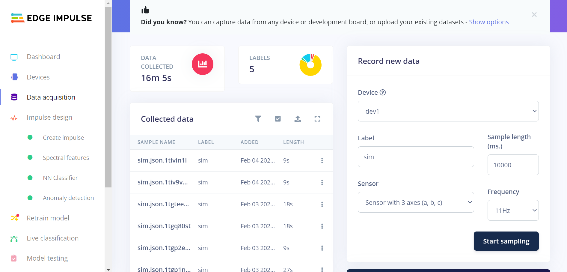
Sampling under Data acquisition in Edge Impulse studio
Observe the received sample data on the raw data graph under the panel. The observed signal depends on the acceleration readouts.
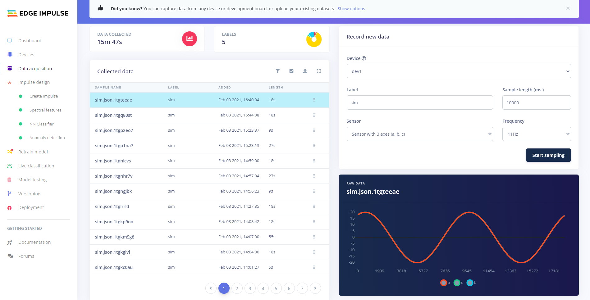
Sampling example
Porting guide
You can port the nRF Machine Learning application to any board available in the nRF Connect SDK or Zephyr.
Create the board-specific directory in applications/machine_learning/configuration/ and add the application configuration files there.
See the Configuration for detailed information about the nRF Machine Learning application configuration.
Dependencies
The application uses the following Zephyr drivers and libraries:
The application uses the following nRF Connect SDK libraries and drivers:
The sample also uses the following secure firmware component:
In addition, you can use the Bluetooth: Central UART sample together with the application. The sample is used to receive data over NUS and forward it to the host over UART.