 |
nRF51 SDK - S210 SoftDevice
|
|
nRF51 SDK - S210 SoftDevice
|
The ANT-FS client device simulator example illustrates the basic operations of an ANT-FS client.
This example supports all three methods of authentication defined in the ANT-FS specification: pairing, passkey and pass-thru. It also supports the simulation of downloading, uploading and erasing files. Other functionality that is not defined in the ANT-FS specification, such as file system implementation and data decoding/encoding are outside of scope of this implementation.
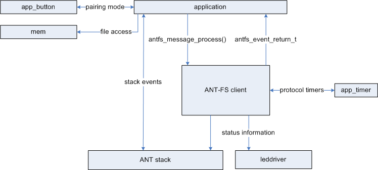
The general architecture of the ANT-FS client device simulator is illustrated in the picture below.
The following compile time configuration options are available to suite various ANT-FS implementations:
This example implements the pairing, pass key and pass-thru authentication methods, which can be enabled using compile switches. All three authentication methods are enabled by default. Upload functionality can also be enabled through a compile switch and it is by default turned on. The compile switches can be set on antfs.c and are listed below.
To establish communication, the host and client devices shall have corresponding configurations. The host device may wish to wildcard any of the fields in the Channel ID and Client Identifier by setting them to zero, but the network key and RF channel frequency shall be the same. The channel period of the client need not match the channel period of the host.
A simple user interface exists consisting of 2 keypad buttons, which are active during pairing authentication for user to accept or reject the authentication, and 2 LEDs which are active during reception of EVENT_TX and pairing authentication mode. LED1 been toggled for every EVENT_TX received from the and stack and LED2 turned on when in pairing authentication mode. The LEDs can be configured in the leddriver.c file.
The ANT-FS client device simulator executes automatically through each ANT-FS layer, as per the commands received from the ANT-FS host. User interaction is only required when using pairing authentication, to confirm or reject a pairing request.
Once a ANT-FS host detects a client with ANT channel and ANT-FS client parameters matching its search criteria, it will send a Link command to the client, specifying the Link RF channel frequency and channel period. The client will automatically switch to the new frequency and channel period, and indicate in its beacon that it has moved to the Authentication stage.
Once both the ANT-FS client and host are in the authentication layer the host can send a request to client device for pairing. The ANT-FS client example supports three methods of authentication: pairing, passkey and pass-thru. When using the passkey and pass-thru authentication methods, the client will automatically accept or reject the authentication as outlined by the ANT-FS specification. Intervention from the user is only required when using the pairing authentication method. If the client receives a pairing request from the host, it will turn on a LED to let the user know that a host device wishes to pair with it. The user can accept or reject the pairing request by pressing the one of the appropriate buttons. If no response from the user is received before the pairing timeout expires, the request will be rejected.
A sample directory structure is implemented in this example, however, no actual files or file systems are present in the example. The client will send the directory to the host if it receives a request to download the directory (file index0). When the host requests a download for any other files, the client will check if the file exists in its directory, and if there is permission to download that file. If the file can be downloaded, the client will simulate a file by sending sequential data with size matching the requested file size; otherwise, it will reject the download.
When the host requests an upload, the client will check if the file index exists in its directory, if there is permission to write on that file, and if there is enough space to write the requested data. Once the client sends a response accepting the upload request, the host can start uploading data. The device simulator does not include actual files, so data is not written to memory; however, the client keeps track of the CRC of the received data to verify the integrity of the upload.
If the client receives a request to erase a file, it will check in its directory to see if the file exists and if there is permission to erase that file. As there are no actual files to delete in this example, if the file can be erased, the client will simply send a response to the host indicating the file was erased; otherwise, it will reject the request.
The ANT-FS client device simulator will trace out ANT-FS protocol state information to UART when AN-FS protocol events occur. The UART peripheral can be configured in simple_uart.c file.
The following compile time configuration options are available to assist in the development phase of the ANT-FS client implementation:
The name of the example for PCA10028 is ant_fs_client_pca10028, and for PCA10031 it is ant_fs_client_pca10031. If you are not using the Keil Pack Installer, you can find the source code and project file of the example in the following folder: <InstallFolder>\Nordic\nrf51\examples\ant\ant_fs\client
 1.8.3.1
