 |
nRF51 SDK - S210 SoftDevice
|
|
nRF51 SDK - S210 SoftDevice
|
The UART module can be used for control of the UART. The UART module has three modes:
The low power mode will be use RTS/CTS flow control while also use the CTS line as to enter low power mode. The UART peripheral will be turned off whenever the CTS signal from the remote side is high, and when CTS becomes low (active) the UART peripheral will be enabled.
Asynchronous nature
The UART module will receive bytes from the RXD register when an EVENT_RXDRDY interrupt has occurred. The byte will be put into the RX FIFO and can be fetched by the application using app_uart_get. First byte received and placed in the RX FIFO will trigger an APP_UART_DATA_READY event.
The app_uart_put will place the provided byte in the TX FIFO. Bytes in the TX FIFO will be written to the TXD register by the app_uart module. When a byte is successfully transfered an EVENT_TXDRDY interrupt is triggered. The interrupt handler in the app_uart module will fetch the next byte from the FIFO and write it to the TXD register. The application can call app_uart_put to request transmission of bytes.
Error handling
An error flag is set in the UART peripheral in event of an error during data reception. The error will be propagated to the application event handler as an app_uart_evt_t containing APP_UART_ERROR_SOURCE in the evt_type field. The data.error_source field will contain the original error source information from the UART peripheral register.
In case the RX FIFO is full when data are received an app_uart_evt_t containing APP_UART_NRF_ERROR in the evt_type field will be generated and sent to the application. The event will contain the original error code from the FIFO in the data.error_code field.
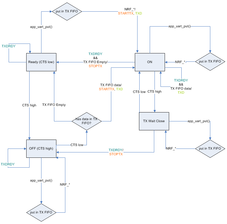
UART Low Power mode with flow control
When UART is configured to use Low Power mode with flow control it will use low power mode when possible. The UART peripheral will be de-activated when the CTS signal from the remote side is set to inactive state. When CTS is set active by the remote side, the UART peripheral will be activated.
The STARTTX register will be enabled when data are available in the TX FIFO and CTS is active.
The application should use app_uart_get_connection_state to ensure that the nRF51 chip only power off when the UART peripheral is disconnected. When the nRF51 chip is in power off mode the remote side can wake up the nRF51 chip by setting the CTS to active state.
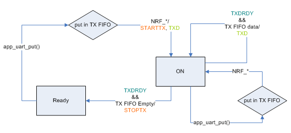
     When using the app_uart module without flow control the UART will not use GPIOTE. CTS will
     not work as a signal for the UART to stop the RX peripheral. Thus the UART RX will
     always be on.
 1.8.3.1
