 |
nRF51 SDK - S110 SoftDevice
|
|
nRF51 SDK - S110 SoftDevice
|
The DTM application enables the DTM test functions described in Bluetooth Specification Version 4.0, Vol. 6, Part F.
The purpose of DTM is to test the operation of the radio at the physical level, such as:
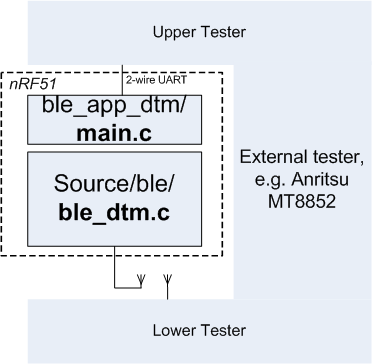
Test procedures are defined the document "Bluetooth Low Energy RF PHY Test Specification", Document no RF-PHY.TS/4.0.0. Conformance tests are carried out by dedicated test equipment (such as the Anritsu MT8852 or similar), the nRF51 with the DTM application as the DUT.
The nRF51 DTM application includes two parts:
The DTM application contains a driver for a 2-wire UART interface, mapping two-octet commands and events as specified by the BLE DTM specification to the dtmlib.
The name of the example is direct_test_mode_s110_pca10028. If you are not using the Keil Pack Installer, you can find the source code and project file of the example in the following folder: <InstallFolder>\Nordic\nrf51\examples\dtm\direct_test_mode
Source code and project file for the ble_dtm module can be found in the following folder: <InstallFolder>\Nordic\nrf51\components\ble\ble_dtm
The implementation is self-contained and requires no BLE protocol stack for its operation. The MPU is initialized in the standard way (files startup_nRF51502.s and system_nRF51502.c. The dtmlib function dtm_init() will do all configuration of interrupts, timers and radio. Initialization of the UART is done by the dtm_serial2w code.
main.c may be replaced with other interface implementations, such as an HCI interface, USB, or other interface required by the Upper Tester.
The interface to the Lower Tester uses the antenna connector of the nRF51. While in principle an aerial may be used, conformance tests cover reading the transmission power delivered by the DUT; hence a coax connection between the DUT and the Lower Tester is employed for all conformance testing.
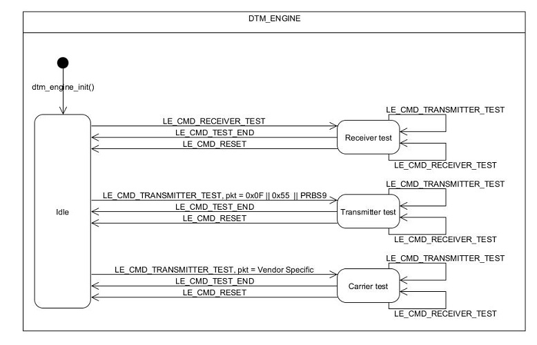
ble_dtm.c function dtm_cmd() implements the four commands defined by the BLE standard
In the dtm_cmd() interface, each of the parameters (cmd,freq, length, payload) is a word size value. Note that the currently supported parameter values are limited to those defined for BLE. (HCI allows a greater value range for use with BR/EDR.)
The following DTM events are polled using the dtm_event_get() function:
The BLE 2-wire UART DTM interface standard reserves Packet Type (payload parameter) binary value '11' for a Vendor Specific Packet Payload. The dtm_serial2w adaptation layer maps this to value 0xFFF..FFF in the dtm_cmd() interface. The rationale for this mapping is to allow later extensions to a 4-bit Packet Type field, as specified in the HCI interface and in the DTM PDU layout.
The Vendor Specific payload (parameter 4) is interpreted as follows:
If Command, parameter 1, is set to Transmitter Test (binary '10') and parameter 4, payload, to Vendor Specific (binary '11' in the 2wire physical interface, all bits set to 1 in the dtmlib interface):
main.c is a sample adaptation layer, implementing the UART interface as specified in Volume 6, part F, chapter 3 of the Bluetooth specification.
The default selection of GPIO pins are pin 11 for RX and pin 9 for TX. These defaults are defined in <InstallFolder>\Nordic\nrf51\examples\bsp\pca10028.h and can be changed by editing the values of the symbols RX_PIN_NUMBER and TX_PIN_NUMBER.
Conformance testing is done using a certified tester. The setup depends on the actual tester, and details about the test operation must be found from the tester documentation.
The BLE DTM UART interface standard specifies:
The default bit rate of the DTM UART driver is 19200 bps, which is supported by most certified testers.
 1.8.3.1
