System integration overview of BLE S110 SoftDevice serialization.
More...
BLE S110 SoftDevice Serialization: System Integration
The image below shows the internal architecture of a serialized BLE S110 SoftDevice.
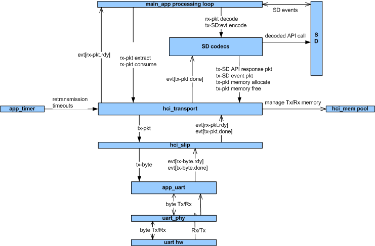
Internal architecture of a serialized BLE S110 SoftDevice.
The image below shows the various threads of execution within the serialized BLE S110 Connectivity Chip.
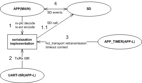
Various threads of execution within the serialized BLE S110 Connectivity Chip.
- SoftDevice command decode and event encode context: MAIN priority context
1.1 SoftDevice command API call as an output of command decode: MAIN priority context
- UART TX/RX ISR calls: APP-LO priority context
- hci_transport retransmission timeout context: APP-LO priority context
- SoftDevice events: MAIN priority context
The image below shows an example internal architecture of an application chip controlling the serialized BLE S110 SoftDevice.
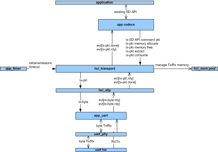
An example of internal architecture of an application chip.
The image below shows an example of various threads of execution which could be executing within an application chip controlling the serialized BLE S110 SoftDevice.
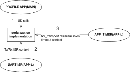
An example of various threads of execution within the application chip.
- SoftDevice calls: MAIN priority context
- UART TX/RX ISR calls: APP-LO priority context
- hci_transport retransmission timeout context: APP-LO priority context
- Note
- The current application chip reference design has been validated using the priority context setup as defined in the above figure. Any deviation from this model can lead to undefined behavior.
The image below shows an MSC of a single basic TX path cycle.
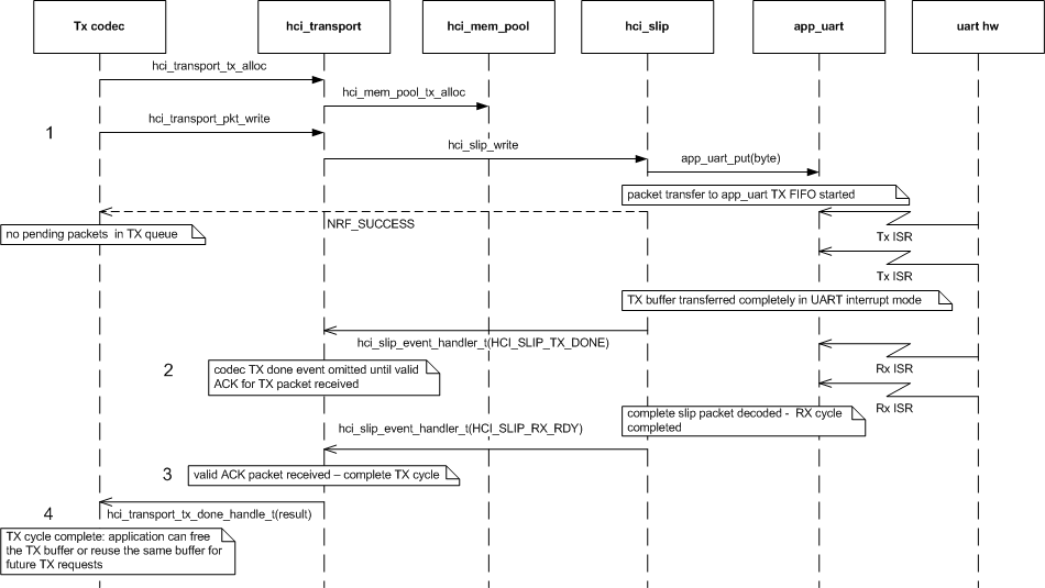
Basic TX path cycle.
- TX codec allocates TX packet memory and issues a packet write request. Request is processed throughout the stack and asynchronous packet write to the UART hardware is started. TX codec receives the status of the request via return code (NRF_SUCCESS), which informs it that a packet was added to the transmission queue and an event will be send upon transmission completion.
- TX buffer is eventually transferred completely and a corresponding event gets propagated to hci_transport which will omit propagating it to TX codec until a valid ACK for the TX packet is received.
- Valid ACK for TX packet is received, which will complete the TX cycle and is reported to the TX codec.
- TX codec received the information of a completed TX cycle and can free the corresponding TX buffer or reuse it for future TX requests.
The image below shows an MSC of a TX path cycle where TX path is 1st stopped due TX queue been filled up and after correct event reception resumed.
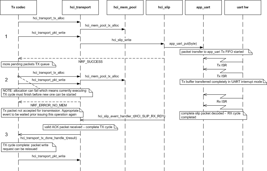
TX path queue full cycle.
- TX codec allocates TX packet memory and issues a packet write request. Request is processed throughout the stack and asynchronous packet write to the UART hardware is started. TX codec receives the status of the request via return code (NRF_SUCCESS), which informs it that a packet was added to the transmission queue and an event will be send upon transmission completion.
- TX codec allocates new TX packet memory and issues a new packet write request while the previous request is still in progress. This request will fail (NRF_ERROR_NO_MEM) because the transmission queue is full and the packet was not added. Before issuing this operation again the appropriate event needs to occur.
- Valid ACK for the TX packet is received. This completes the TX cycle and is reported to the TX codec which can re-issue the packet write request.
The image below shows an MSC of a single basic RX path cycle.
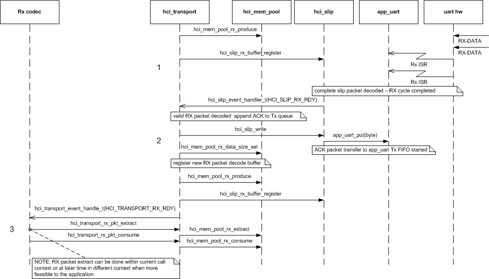
Basic RX path cycle.
- Free RX memory block is produced by hci_transport and given to hci_slip layer to be used as an RX buffer. RX data is received through the UART, which will be decoded by the hci_slip layer and an event is send to hci_transport layer once a valid slip packet has been received.
- Valid RX packet is decoded by hci_transport layer and corresponding ACK packet is written to TX queue (if available space exists otherwise it is discarded). Actual length of the received RX packet is stored to the corresponding RX memory block. New free RX memory block is produced by hci_transport and given to hci_slip layer to be used as RX buffer.
- An event is send to the RX codec when a valid RX packet is received. The received packet is extracted and processed by the RX codec allowing the memory to be reused by the hci_transport layer.