 |
nRF51 SDK
|
|
nRF51 SDK
|
The DFU Bootloader project uses a memory layout similar to the of the nRF51822 Bluetooth examples, except that the memory region from 0x3C800-0x40000 has been reserved for the DFU Bootloader, and application data is written below the bootloader instead of at the end of the flash. The memory layout can be seen in Figure 1.
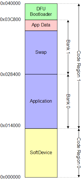
The table below lists the memory ranges when using an S110 SoftDevice. The SoftDevice will be using region 1 memory spanning from address 0x0 to 0x14000. Region 1 will contain the application and bootloader.
| Memory Range | Usage |
|---|---|
| 0x0003C800 - 0x00040000 | Code Region 1: DFU Bootloader, and data |
| 0x00014000 - 0x0003C800 | Code Region 1: Application Code (BANK 0), Swap (BANK 1), and data |
| 0x00000000 - 0x00014000 | Code Region 0: SoftDevice |
The Application Data size is default set to 0x0000, meaning that all Application Data will be erased during a Device Firmware Update procedure. This behaviour can be configured by the developer to ensure persistency of the Application Data by specifying:
to a different value. Specifying DFU_APP_DATA_RESERVED to 0x1000 will ensure that 4 pages of Application Data are preserved during the DFU procedure.
The steps of the update procedure are illustrated in the figures below.
| Detailed description | |
|---|---|
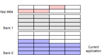
| Figure 2 | Before the Bootloader initializes, the active Application resides in Bank 0, while the content of Bank 1 is undefined. |
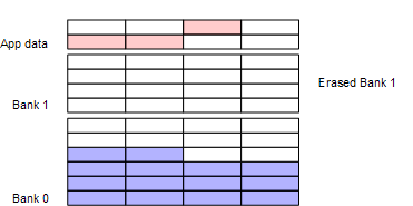
| Figure 3 | As a first step the Bootloader erases Bank 1, where the received new Application will be copied. This ensures that if the update is interrupted the old Application is still available. |
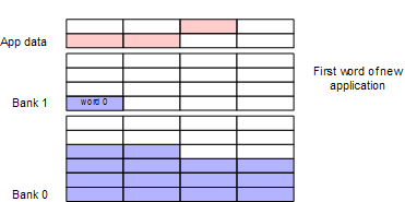
| Figure 4 | During transfer the received packets of the new Application are written into Bank 1. It is assumed that the packets are transmitted in the right order. |
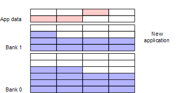
| Figure 5 | After all packets of the new Application are received, both the old and the new Application are present in the memory. This ensures that fallback to the old Application is possible if the new Application cannot be activated. |
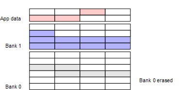
| Figure 6 | If the activation of the new Application is successful, Bank 0 is erased to accommodate the new Application. If DFU_APP_DATA_RESERVED is set, Application Data will be preserved. |
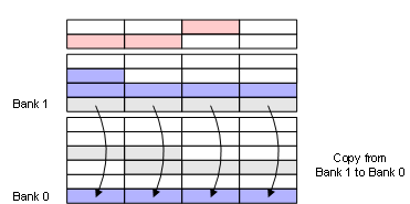
| Figure 7 | As part of of activating the new Application it is moved from Bank 1 to Bank 0. |
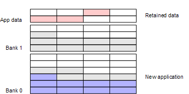
| Figure 8 | After the copy procedure is complete, the system can be reset with running the new Application in Bank 0. Bank 1 won't be erased until the Bootloader initializes again. |
| Figure 9 | If Application Data from the old Application was preserved, the new Application will append any new data written. |