Important: We're excited to introduce our new technical documentation platform docs.nordicsemi.com, currently in Beta version. We invite you to explore it and share your feedback. Read more on our DevZone blog.
This light switch sample demonstrates the usage of the Matter application layer to build a switch device that binds with lighting devices and changes the state of their LEDs.
You can use this sample as a reference for creating your own application.
When configured together with the Matter light bulb sample (or other lighting sample) and when using a Matter controller, the light switch can control one light bulb directly or a group of light bulbs remotely over a Matter network built on top of a low-power, 802.15.4 Thread, or on top of a Wi-Fi network.
Support for both Thread and Wi-Fi is mutually exclusive and depends on the hardware platform, so only one protocol can be supported for a specific light switch device.
Depending on the network you choose:
In case of Wi-Fi, this device works in the Legacy Power Save mode.
This means that the device sleeps most of the time and wakes up on each Delivery Traffic Indication Message (DTIM) interval to poll for pending messages.
For this sample to work, you also need at least one Matter light bulb sample programmed to another supported development kit.
To commission the device and run all required commands, you need also a Matter controller.
By default, this sample is configured to use the CHIP Tool as Matter controller.
See the Working with the CHIP Tool page in the Matter documentation for the CHIP Tool’s setup information.
If you decide to use Matter CLI commands, you also need a USB cable for the serial connection.
Note
Matter requires the GN tool.
If you are updating from the nRF Connect SDK version earlier than v1.5.0, see the GN installation instructions.
The sample controls the state of the LED 2 on connected light bulbs devices.
After configuring the light switch sample, the lighting devices get proper Access Control List from the Matter controller to start receiving commands sent from the light switch.
Then, the light switch device prepares a new binding table to be able to discover light bulb devices and perform Binding.
After the binding is complete, the application can control the state of the connected lighting devices in one of the following ways:
With a single light bulb, it uses a Certificate-Authenticated Session Establishment session (CASE session) for direct communication with the single light bulb.
With a group of light bulbs, it uses multicast messages sent through the IPv6 network using Group communication with all light bulbs in the group.
The Access Control List (ACL) is a list related to the Access Control cluster.
The list contains rules for managing and enforcing access control for a node’s endpoints and their associated cluster instances.
In this sample’s case, this allows the lighting devices to receive messages from the light switch and run them.
You can read more about ACLs on the Access Control Guide in the Matter documentation.
Group communication (groupcast or multicast) refers to messages and commands sent to the address of a group that includes multiple devices with the same Groups cluster.
The cluster manages the content of a node-wide Group Table that is part of the underlying interaction layer.
This is done on per endpoint basis.
After creating the Group cluster with specific ID and Name, a device gets its own IPv6 multicast address and is ready to receive groupcast commands.
In this sample, the light switch device is able to create a groupcast message and send it to the chosen IPv6 multicast address.
This allows the light switch more than one lighting devices at the same time.
Note
Writing the groupcast table on the devices blocks sending unicast commands.
If you want to go back to the original state, perform factory reset of the device.
Binding refers to establishing a relationship between endpoints on the local and remote nodes.
With binding, local endpoints are pointed and bound to the corresponding remote endpoints.
Both must belong to the same cluster type.
Binding lets the local endpoint know which endpoints are going to be the target for the client-generated actions on one or more remote nodes.
In this sample, the light switch controls one or more lighting devices, but does not know the remote endpoints of the lights (on remote nodes).
Using binding, the light switch device updates its Binding cluster with all relevant information about the lighting devices, such as their IPv6 address, node ID, and the IDs of the remote endpoints that contains the On/Off cluster and the LevelControl cluster, respectively.
The sample does not use a single prj.conf file.
Configuration files are provided for different build types, and they are located in the sample root directory.
Before you start testing the application, you can select one of the build types supported by the application.
Debug version of the application; can be used to enable additional features for verifying the application behavior, such as logs or command-line shell.
You can add support for the nRF21540 front-end module to this sample by using one of the following options, depending on your hardware:
Build the sample for one board that contains the nRF21540 FEM, such as nrf21540dk_nrf52840.
Manually create a devicetree overlay file that describes how FEM is connected to the nRF5 SoC in your device.
See Set devicetree overlays for different ways of adding the overlay file.
Provide nRF21540 FEM capabilities by using a shield, for example the nRF21540 EK shield that is available in the nRF Connect SDK.
In this case, build the project for a board connected to the shield you are using with an appropriate variable included in the build command, for example SHIELD=nrf21540ek.
This variable instructs the build system to append the appropriate devicetree overlay file.
To build the sample in the nRF Connect for VS Code IDE for an nRF52840 DK with the nRF21540 EK attached, add the shield variable in the build configuration’s Extra CMake arguments and rebuild the build configuration.
For example: -DSHIELD=nrf21540ek.
To build the sample from the command line for an nRF52840 DK with the nRF21540 EK attached, use the following command within the sample directory:
west build -b nrf52840dk_nrf52840 -- -DSHIELD=nrf21540ek
See Programming nRF21540 EK for information about how to program when you are using a board with a network core, for example nRF5340 DK.
Each of these options adds the description of the nRF21540 FEM to the devicetree.
See Working with RF front-end modules for more information about FEM in the nRF Connect SDK.
To add support for other front-end modules, add the respective devicetree file entries to the board devicetree file or the devicetree overlay file.
You can enable over-the-air Device Firmware Upgrade only on hardware platforms that have external flash memory.
Currently only nRF52840 DK, nRF5340 DK and nRF7002 DK support Device Firmware Upgrade feature.
The sample supports over-the-air (OTA) device firmware upgrade (DFU) using one of the two following protocols:
Matter OTA update protocol that uses the Matter operational network for querying and downloading a new firmware image.
Simple Management Protocol (SMP) over Bluetooth® LE.
In this case, the DFU can be done either using a smartphone application or a PC command line tool.
Note that this protocol is not part of the Matter specification.
In both cases, MCUboot secure bootloader is used to apply the new firmware image.
The DFU over Matter is enabled by default.
The following configuration arguments are available during the build process for configuring DFU:
To configure the sample to support the DFU over Matter and SMP, use the -DCONFIG_CHIP_DFU_OVER_BT_SMP=y build flag.
When building on the command line, run the following command with build_target replaced with the build target name of the hardware platform you are using (see Requirements), and dfu_build_flag replaced with the desired DFU build flag:
west build -b build_target -- dfu_build_flag
For example:
west build -b nrf52840dk_nrf52840 -- -DCONFIG_CHIP_DFU_OVER_BT_SMP=y
The Device Firmware Upgrade (DFU) for the nRF54L15 PDK is exclusively available for the release build configuration and is limited to using the internal MRAM for storage.
This means that both the currently running firmware and the new firmware to be updated must be stored within the device’s internal flash memory.
Currently, there is no support for utilizing external flash memory for this purpose.
To build the sample with DFU support, use the -DCONF_FILE=prj_release.conf flag in your CMake build command.
The following is an example command to build the sample with support for OTA DFU only:
west build -b nrf54l15pdk_nrf54l15_cpuapp -- -DCONF_FILE=prj_release.conf
If you want to build the sample with support for both OTA DFU and SMP DFU, use the following command:
west build -b nrf54l15pdk_nrf54l15_cpuapp -- -DCONF_FILE=prj_release.conf -DCONFIG_CHIP_DFU_OVER_BT_SMP=y
You can disable DFU support for the release build configuration to double available application memory space.
Do this by setting the CONFIG_CHIP_DFU_OVER_BT_SMP and CONFIG_CHIP_OTA_REQUESTOR Kconfig options to n, and removing the pm_static_nrf54l15pdk_nrf54l15_cpuapp_release.yml file.
For example:
west build -b nrf54l15pdk_nrf54l15_cpuapp -- -DCONF_FILE=prj_release.conf -DCONFIG_CHIP_DFU_OVER_BT_SMP=n -DCONFIG_CHIP_OTA_REQUESTOR=n
In this sample, the factory data support is enabled by default for all build types except for the target board nRF21540 DK.
This means that a new factory data set will be automatically generated when building for the target board.
To disable factory data support, set the following Kconfig options to n:
The nRF54L15 PDK revision v0.3.0 uses a different numbering system for buttons and LEDs compared to previous boards.
All numbers start from 0 instead of 1, as was the case previously.
This means that LED1 in this documentation refers to LED0 on the nRF54L15 PDK board, LED2 refers to LED1, Button 1 refers to Button 0, and so on.
For the nRF54L15 PDK revision v0.2.1, the numbering of buttons and LEDs is the same as on the nRF52840 DK and nRF5340 DK boards.
LED 1:
Shows the overall state of the device and its connectivity.
The following states are possible:
Short Flash On (50 ms on/950 ms off) - The device is in the unprovisioned (unpaired) state and is waiting for a commissioning application to connect.
Rapid Even Flashing (100 ms on/100 ms off) - The device is in the unprovisioned state and a commissioning application is connected over Bluetooth LE.
Solid On - The device is fully provisioned.
LED 2:
The LED starts blinking evenly (500 ms on/500 ms off) when the Identify command of the Identify cluster is received on the endpoint 1.
The command’s argument can be used to specify the duration of the effect.
All LEDs:
Blink in unison when the factory reset procedure is initiated.
Button 1:
Depending on how long you press the button:
If pressed for less than three seconds:
If the device is not provisioned to the Matter network, it initiates the SMP server (Simple Management Protocol) and Bluetooth LE advertising for Matter commissioning.
After that, the Device Firmware Update (DFU) over Bluetooth Low Energy can be started.
(See Upgrading the device firmware.)
Bluetooth LE advertising makes the device discoverable over Bluetooth LE for the predefined period of time (15 minutes by default).
If the device is already provisioned to the Matter network it re-enables the SMP server.
After that, the DFU over Bluetooth Low Energy can be started.
(See Upgrading the device firmware.)
If pressed for more than three seconds, it initiates the factory reset of the device.
Releasing the button within a 3-second window of the initiation cancels the factory reset procedure.
Button 2:
Controls the light on the bound lighting device.
Depending on how long you press the button:
If pressed for less than 0.5 seconds, it changes the light state to the opposite one on the bound lighting device (light bulb).
If pressed for more than 0.5 seconds, it changes the brightness of the light on the bound lighting bulb device (light bulb).
The brightness is changing from 0% to 100% with 1% increments every 300 milliseconds as long as Button 2 is pressed.
SEGGER J-Link USB port:
Used for getting logs from the device or for communicating with it through the command-line interface.
If you build the application using the debug build type, you can use a series of commands to control the light switch device.
These commands can be sent to one device (unicast) or a group of devices (groupcast).
After building this and the Matter Light Bulb samples, and programming them to the development kits, complete the following steps:
Note
In both samples (light switch and light bulb), a Bluetooth LE discriminator is set with the same value by default (hexadecimal: 0xF00; decimal: 3840).
This means that only one uncommissioned device can be powered up before commissioning.
If both are powered up at the same time, the CHIP Tool can commission a random device and the node ID assignment is also random.
When one device is commissioned, power up the next device and perform the commissioning.
To avoid this unclear situation, you can set up your unique discriminator in src/chip_project_config.h file by changing CHIP_DEVICE_CONFIG_USE_TEST_SETUP_DISCRIMINATOR value.
Then build an example and commission with your unique discriminator.
Connect the kit to the computer using a USB cable.
The kit is assigned a COM port (Windows) or ttyACM device (Linux), which is visible in the Device Manager.
Open a serial port connection to the kit using a terminal emulator that supports VT100/ANSI escape characters (for example, nRF Connect Serial Terminal).
See Testing and optimization for the required settings and steps.
If devices were not erased during the programming, press and hold Button 1 on each device until the factory reset takes place.
On each device, press Button 1 to start the Bluetooth LE advertising.
Commission devices to the Matter network.
See Commissioning the device for more information.
During the commissioning process, write down the values for the light switch node ID and the light bulb node ID (or IDs, if you are using more than one light bulb).
These IDs are going to be used in the next steps (<light_switch_node_ID> and <light_bulb_node_ID>, respectively).
Use the CHIP Tool (“Writing ACL to the accesscontrol cluster” section) to add proper ACL for the light bulb device.
Depending on the number of the light bulb devices you are using, use one of the following commands, with <light_switch_node_ID> and <light_bulb_node_ID> values from the previous step about commissioning:
If you are using only one light bulb device, run the following command for the light bulb device:
If you are using more than one light bulb device, connect all devices to the multicast group by running the following command for each device, including the light switch:
After preparing devices for testing, you can test the communication either of a single light bulb or of a group of light bulbs with the light switch (but not both a single device and a group at the same time).
Complete the following steps:
On the light switch device, use buttons to control the bound light bulbs:
On the light switch device, press Button 2 to turn off the LED 2 located on the bound light bulb device.
On the light switch device, press Button 2 to turn on the light again.
LED 2 on the light bulb device turns back on.
Press Button 2 and hold it for more than 0.5 seconds to test the dimmer functionality.
LED 2 on the bound light bulb device changes its brightness from 0% to 100% with 1% increments every 300 milliseconds as long as Button 2 is pressed.
Using the terminal emulator connected to the light switch, run the following Matter CLI commands:
Write the following command to turn on LED 2 located on the bound light bulb devices:
For a single bound light bulb:
matterswitchonoffon
For a group of light bulbs:
matterswitchgroupsonoffon
Write the following command to turn on LED 2 located on the bound light bulb device:
To commission the device, go to the Testing Matter in the nRF Connect SDK page and complete the steps for the Matter network environment and the Matter controller you want to use.
After choosing the configuration, the guide walks you through the following steps:
Only if you are configuring Matter over Thread: Configure the Thread Border Router.
Build and install the Matter controller.
Commission the device.
Send Matter commands that cover scenarios described in the Testing section.
Before starting the commissioning procedure, the device must be made discoverable over Bluetooth LE.
By default, the device is not discoverable automatically upon startup.
Press Button 1 to enable the Bluetooth LE advertising.
When you start the commissioning procedure, the controller must get the onboarding information from the Matter accessory device.
The onboarding information representation depends on your commissioner setup.
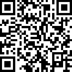
For this sample, you can use one of the following onboarding information formats to provide the commissioner with the data payload that includes the device discriminator and the setup PIN code:
Scan the following QR code with the app for your ecosystem:
MT:4CT9142C00KA0648G00
34970112332
When the factory data support is enabled, the onboarding information will be stored in the build directory in the following files:
The factory_data.png file includes the generated QR code.
The factory_data.txt file includes the QR Code Payload and the manual pairing code.
This data payload also includes test Device Attestation, with test Certification Declaration, Product ID, and Vendor ID.
These are used for Device Attestation within commissioning, and you can generate your own test Certification Declaration when you work on Matter end product.