Important: We're excited to introduce our new technical documentation platform docs.nordicsemi.com, currently in Beta version. We invite you to explore it and share your feedback. Read more on our DevZone blog.
This light bulb sample demonstrates the usage of the Matter application layer to build a white dimmable light bulb device.
This device works as a Matter accessory device, meaning it can be paired and controlled remotely over a Matter network built on top of a low-power, 802.15.4 Thread network or on top of a Wi-Fi network.
Support for both Thread and Wi-Fi is mutually exclusive and depends on the hardware platform, so only one protocol can be supported for a specific light bulb device.
You can use this sample as a reference for creating your own application.
Note
This sample is self-contained and can be tested on its own.
However, it is required when testing the Matter light switch sample.
The sample can also communicate with AWS IoT Core over a Wi-Fi network using the nRF7002 DK.
For more details, see the AWS IoT integration section.
If you want to commission the light bulb device and control it remotely, you also need a Matter controller device configured on PC or mobile.
This requires additional hardware depending on the setup you choose.
Note
Matter requires the GN tool.
If you are updating from the nRF Connect SDK version earlier than v1.5.0, see the GN installation instructions.
The sample uses buttons to test changing the light bulb and device states, and LEDs to show the state of these changes.
You can test it in the following ways:
Standalone, by using a single DK that runs the light bulb application.
Remotely over the Thread or Wi-Fi, which requires more devices.
The remote control testing requires a Matter controller that you can configure either on a PC or a mobile device (for remote testing in a network).
You can enable both methods after building and running the sample.
By default, the Matter accessory device has no IPv6 network configured.
You must pair it with the Matter controller over Bluetooth® LE to get the configuration from the controller to use the device within a Thread or Wi-Fi network.
The controller must get the Onboarding information from the Matter accessory device and provision the device into the network.
For details, see the Commissioning the device section.
The sample does not use a single prj.conf file.
Configuration files are provided for different build types, and they are located in the sample root directory.
Before you start testing the application, you can select one of the build types supported by the application.
Debug version of the application; can be used to enable additional features for verifying the application behavior, such as logs or command-line shell.
You can enable over-the-air Device Firmware Upgrade only on hardware platforms that have external flash memory.
Currently only nRF52840 DK, nRF5340 DK and nRF7002 DK support Device Firmware Upgrade feature.
The sample supports over-the-air (OTA) device firmware upgrade (DFU) using one of the two following protocols:
Matter OTA update protocol that uses the Matter operational network for querying and downloading a new firmware image.
Simple Management Protocol (SMP) over Bluetooth® LE.
In this case, the DFU can be done either using a smartphone application or a PC command line tool.
Note that this protocol is not part of the Matter specification.
In both cases, MCUboot secure bootloader is used to apply the new firmware image.
The DFU over Matter is enabled by default.
The following configuration arguments are available during the build process for configuring DFU:
To configure the sample to support the DFU over Matter and SMP, use the -DCONFIG_CHIP_DFU_OVER_BT_SMP=y build flag.
When building on the command line, run the following command with build_target replaced with the build target name of the hardware platform you are using (see Requirements), and dfu_build_flag replaced with the desired DFU build flag:
west build -b build_target -- dfu_build_flag
For example:
west build -b nrf52840dk_nrf52840 -- -DCONFIG_CHIP_DFU_OVER_BT_SMP=y
The Device Firmware Upgrade (DFU) for the nRF54L15 PDK is exclusively available for the release build configuration and is limited to using the internal MRAM for storage.
This means that both the currently running firmware and the new firmware to be updated must be stored within the device’s internal flash memory.
Currently, there is no support for utilizing external flash memory for this purpose.
To build the sample with DFU support, use the -DCONF_FILE=prj_release.conf flag in your CMake build command.
The following is an example command to build the sample with support for OTA DFU only:
west build -b nrf54l15pdk_nrf54l15_cpuapp -- -DCONF_FILE=prj_release.conf
If you want to build the sample with support for both OTA DFU and SMP DFU, use the following command:
west build -b nrf54l15pdk_nrf54l15_cpuapp -- -DCONF_FILE=prj_release.conf -DCONFIG_CHIP_DFU_OVER_BT_SMP=y
You can disable DFU support for the release build configuration to double available application memory space.
Do this by setting the CONFIG_CHIP_DFU_OVER_BT_SMP, and CONFIG_CHIP_OTA_REQUESTOR Kconfig options to n.
For example:
west build -b nrf54l15pdk_nrf54l15_cpuapp -- -DCONF_FILE=prj_release.conf -DCONFIG_CHIP_DFU_OVER_BT_SMP=n -DCONFIG_CHIP_OTA_REQUESTOR=n
You can add support for the nRF21540 front-end module to this sample by using one of the following options, depending on your hardware:
Build the sample for one board that contains the nRF21540 FEM, such as nrf21540dk_nrf52840.
Manually create a devicetree overlay file that describes how FEM is connected to the nRF5 SoC in your device.
See Set devicetree overlays for different ways of adding the overlay file.
Provide nRF21540 FEM capabilities by using a shield, for example the nRF21540 EK shield that is available in the nRF Connect SDK.
In this case, build the project for a board connected to the shield you are using with an appropriate variable included in the build command, for example SHIELD=nrf21540ek.
This variable instructs the build system to append the appropriate devicetree overlay file.
To build the sample in the nRF Connect for VS Code IDE for an nRF52840 DK with the nRF21540 EK attached, add the shield variable in the build configuration’s Extra CMake arguments and rebuild the build configuration.
For example: -DSHIELD=nrf21540ek.
To build the sample from the command line for an nRF52840 DK with the nRF21540 EK attached, use the following command within the sample directory:
west build -b nrf52840dk_nrf52840 -- -DSHIELD=nrf21540ek
See Programming nRF21540 EK for information about how to program when you are using a board with a network core, for example nRF5340 DK.
Each of these options adds the description of the nRF21540 FEM to the devicetree.
See Working with RF front-end modules for more information about FEM in the nRF Connect SDK.
To add support for other front-end modules, add the respective devicetree file entries to the board devicetree file or the devicetree overlay file.
In this sample, the factory data support is enabled by default for all build types except for the target board nRF21540 DK.
This means that a new factory data set will be automatically generated when building for the target board.
To disable factory data support, set the following Kconfig options to n:
The sample can be configured to communicate with AWS IoT Core to control attributes in supported clusters on the device.
After a connection has been established, the sample will mirror these attributes in the AWS IoT shadow document.
This makes it possible to remotely control the device using the AWS IoT Device Shadow Service.
The supported attributes are OnOff from the OnOff cluster and CurrentLevel from the LevelControl cluster.
The following figure illustrates the relationship between the AWS IoT integration layer and the light bulb sample:
Import the certificates to the light_bulb/src/aws_iot_integration/certs folder.
The certificates will vary in size depending on the method you chose when generating the certificates.
Due to this, you might need to increase the value of the CONFIG_MBEDTLS_SSL_OUT_CONTENT_LEN option to be able to establish a connection.
Build the sample using the following command:
west build -p -b nrf7002dk_nrf5340_cpuapp -- -DEXTRA_CONF_FILE="overlay-aws-iot-integration.conf"
Flash the firmware and boot the sample.
Connect the kit to the computer using a USB cable.
The kit is assigned a COM port (Windows) or ttyACM device (Linux), which is visible in the Device Manager.
Open a serial port connection to the kit using a terminal emulator that supports VT100/ANSI escape characters (for example, nRF Connect Serial Terminal).
See Testing and optimization for the required settings and steps.
You can also use aws-update-desired00, or aws-update-desired1128(onoff,levelcontrol).
Alternatively, you can alter the device shadow directly through the AWS IoT console.
Observe that the light bulb changes state.
The local changes to the attributes always take precedence over what is set in the shadow’s desired state.
Note
The integration layer has built-in reconnection logic and tries to maintain the connection as long as the device is connected to the internet.
The reconnection interval can be configured using the CONFIG_AWS_IOT_RECONNECTION_INTERVAL_SECONDS option.
The nRF54L15 PDK revision v0.3.0 uses a different numbering system for buttons and LEDs compared to previous boards.
All numbers start from 0 instead of 1, as was the case previously.
This means that LED1 in this documentation refers to LED0 on the nRF54L15 PDK board, LED2 refers to LED1, Button 1 refers to Button 0, and so on.
For the nRF54L15 PDK revision v0.2.1, the numbering of buttons and LEDs is the same as on the nRF52840 DK and nRF5340 DK boards.
LED 1:
Shows the overall state of the device and its connectivity.
The following states are possible:
Short Flash On (50 ms on/950 ms off) - The device is in the unprovisioned (unpaired) state and is waiting for a commissioning application to connect.
Rapid Even Flashing (100 ms on/100 ms off) - The device is in the unprovisioned state and a commissioning application is connected over Bluetooth LE.
Solid On - The device is fully provisioned.
LED 2:
Shows the state of the light bulb.
The following states are possible:
Solid On - The light bulb is on.
Off - The light bulb is off.
Additionally, the LED starts blinking evenly (500 ms on/500 ms off) when the Identify command of the Identify cluster is received on the endpoint 1.
The command’s argument can be used to specify the duration of the effect.
Button 1:
Depending on how long you press the button:
If pressed for less than three seconds:
If the device is not provisioned to the Matter network, it initiates the SMP server (Simple Management Protocol) and Bluetooth LE advertising for Matter commissioning.
After that, the Device Firmware Update (DFU) over Bluetooth Low Energy can be started.
(See Upgrading the device firmware.)
Bluetooth LE advertising makes the device discoverable over Bluetooth LE for the predefined period of time (15 minutes by default).
If the device is already provisioned to the Matter network it re-enables the SMP server.
After that, the DFU over Bluetooth Low Energy can be started.
(See Upgrading the device firmware.)
If pressed for more than three seconds, it initiates the factory reset of the device.
Releasing the button within a 3-second window of the initiation cancels the factory reset procedure.
Button 2:
Changes the light bulb state to the opposite one.
SEGGER J-Link USB port:
Used for getting logs from the device or for communicating with it through the command-line interface.
After building the sample and programming it to your development kit, complete the following steps to test its basic features:
Connect the kit to the computer using a USB cable.
The kit is assigned a COM port (Windows) or ttyACM device (Linux), which is visible in the Device Manager.
Open a serial port connection to the kit using a terminal emulator that supports VT100/ANSI escape characters (for example, nRF Connect Serial Terminal).
See Testing and optimization for the required settings and steps.
Observe that LED 2 is off.
Press Button 2 on the light bulb device.
The LED 2 turns on and the following messages appear on the console:
I: Turn On Action has been initiatedI: Turn On Action has been completed
Press Button 2 again.
The LED 2 turns off and the following messages appear on the console:
I: Turn Off Action has been initiatedI: Turn Off Action has been completed
Keep the Button 1 pressed for more than six seconds to initiate factory reset of the device.
After building this sample and the Matter light switch sample and programming them to the development kits, complete the steps in the following sections to test communication between both devices.
Complete the following steps to bind both devices:
Connect the kit to the computer using a USB cable.
The kit is assigned a COM port (Windows) or ttyACM device (Linux), which is visible in the Device Manager.
Open a serial port connection to the kit using a terminal emulator that supports VT100/ANSI escape characters (for example, nRF Connect Serial Terminal).
See Testing and optimization for the required settings and steps.
If devices were not erased during the programming, press and hold Button 1 on each device until the factory reset takes place.
On each device, press Button 1 to start the Bluetooth LE advertising.
Commission devices to the Matter network.
See Commissioning the device for more information.
During the commissioning process, write down the values for the light switch node ID and the light bulb node ID (or IDs, if you are using more than one light bulb).
These IDs are going to be used in the next steps (<light_switch_node_ID> and <light_bulb_node_ID>, respectively).
Use the CHIP Tool (“Writing ACL to the accesscontrol cluster” section) to add proper ACL for the light bulb device.
Depending on the number of the light bulb devices you are using, use one of the following commands, with <light_switch_node_ID> and <light_bulb_node_ID> values from the previous step about commissioning:
If you are using only one light bulb device, run the following command for the light bulb device:
If you are using more than one light bulb device, connect all devices to the multicast group by running the following command for each device, including the light switch:
After preparing devices for testing, you can test the communication either of a single light bulb or of a group of light bulbs with the light switch (but not both a single device and a group at the same time).
Complete the following steps:
On the light switch device, use buttons to control the bound light bulbs:
On the light switch device, press Button 2 to turn off the LED 2 located on the bound light bulb device.
On the light switch device, press Button 2 to turn on the light again.
LED 2 on the light bulb device turns back on.
Press Button 2 and hold it for more than 0.5 seconds to test the dimmer functionality.
LED 2 on the bound light bulb device changes its brightness from 0% to 100% with 1% increments every 300 milliseconds as long as Button 2 is pressed.
Using the terminal emulator connected to the light switch, run the following Matter CLI commands:
Write the following command to turn on LED 2 located on the bound light bulb devices:
For a single bound light bulb:
matterswitchonoffon
For a group of light bulbs:
matterswitchgroupsonoffon
Write the following command to turn on LED 2 located on the bound light bulb device:
To commission the device, go to the Testing Matter in the nRF Connect SDK page and complete the steps for the Matter over Thread or Matter over Wi-Fi development environment and the Matter controller you want to use.
After choosing the environment configuration, the guide walks you through the following steps:
Configure the Thread Border Router (only for Matter over Thread communication).
Build and install the Matter controller.
Commission the device.
Send Matter commands that cover scenarios described in the Testing section.
Before starting the commissioning procedure, the device must be made discoverable over Bluetooth LE.
The device becomes discoverable automatically upon the device startup, but only for a predefined period of time (15 minutes by default).
If the Bluetooth LE advertising times out, press Button 1 to enable it again.
When you start the commissioning procedure, the controller must get the onboarding information from the Matter accessory device.
The onboarding information representation depends on your commissioner setup.
For this sample, you can use one of the following onboarding information formats to provide the commissioner with the data payload that includes the device discriminator and the setup PIN code:
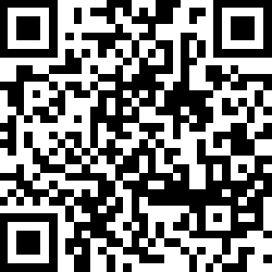
Scan the following QR code with the app for your ecosystem:
MT:6FCJ142C00KA0648G00
34970112332
When the factory data support is enabled, the onboarding information will be stored in the build directory in the following files:
The factory_data.png file includes the generated QR code.
The factory_data.txt file includes the QR Code Payload and the manual pairing code.
This data payload also includes test Device Attestation, with test Certification Declaration, Product ID, and Vendor ID.
These are used for Device Attestation within commissioning, and you can generate your own test Certification Declaration when you work on Matter end product.