The Device Firmware Upgrade over TFTP is an example using the TFTP module and the IoT DFU library to show how to change firmware using IPv6 connectivity.
To demonstrate support for Application IoT DFU on nRF52, Nordic's IPv6 stack is used.
This example implements a simple application, which includes the IoT DFU module to provide the upgrading service as a background process.
- Note
- For demo purposes, see Create DFU images for information about creating your own images.
-
A demo requires an IPv6 TFTP server to download and upload files. For installing a simple TFTP server on Linux see this section.
This example requires you to create new firmware images. For more information, see Create DFU images.
The demo setup and flow diagram are presented in Figure 1.
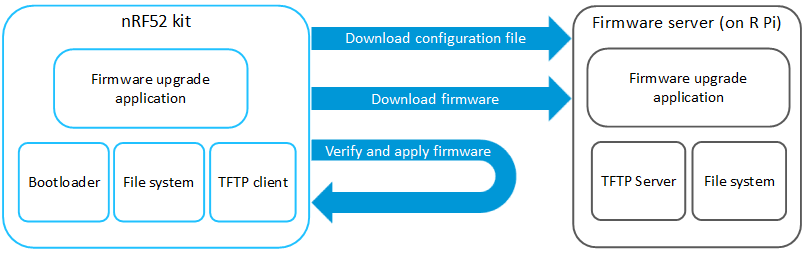
Figure 1: Setup of the App DFU over a TFTP enabled application
Overview
This example demonstrates how Nordic's IPv6 stack can be used for transmitting and receiving new firmware. It uses the TFTP module as a transport layer to transfer new firmware.
The application spends most of the time in normal IDLE mode. In the background, the software configuration file is downloading and checking every 10 seconds. The configuration file is located on the TFTP server and is read to determine when it should download and apply new firmware (application, application with a SoftDevice, or a bootloader). It checks the current CRC16 firmware block and compares it with the values obtained from the configuration file.
Data Exchange MSC
The MSC below provides an overview of the data exchange in the application between the node (nRF52) and the router/cloud in two instances:
- The device already has the correct application.
- There was an upgrade caused by a file configuration modification.
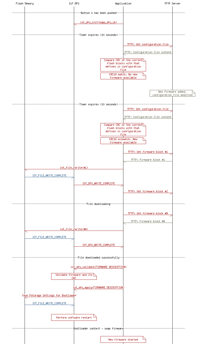
Figure 2: Data Exchange
JSON configuration files
Each device has its own configuration file. The path for those files is created in the following way:
where
- DEV_TYPE is a 16-bit device type number located inside the UICR register. This is usually located at the address 0x10001080 (by default: 65535).
- DEV_ID is a 16-bit device identification number located inside the UICR register. This is usually located at the address 0x10001084 (by default: 65535).
This file should be a JSON formatted object which consists of three parts. One per each firmware type. For example:
{
"app": {
"s": 57443,
"id": 51633
},
"sd": {
"s": 113492,
"id": 31115
},
"bl": {
"s": 13492,
"id": 3633
},
"p": {
"app" : "/dfu/app/app.bin",
"appsd" : "/dfu/app/appsd.bin",
"bl" : "/dfu/app/bl.bin"
}
}
Each part is described by two values and the path to the appropriate firmware block:
- Size of the binary file in bytes.
- ID of the file, which in this example is a CRC16 control sum of a given block image.
- Path to the binary file.
In order to configure new firmware, you should modify the JSON elements to match the new firmware path, size, and its CRC16, and place it in the corresponding field.
- Note
- If the device has an existing application when performing a SoftDevice update, the application is erased. Because IoT DFU is triggered by the application context, the SoftDevice can not be swaped as a single firmware block without an application. See Merge binaries for information on how to merge two binaries into one with a SoftDevice and application. When updating a SoftDevice with an application, the application section in JSON should also be updated to set the correct CRC and size for validation reasons.
Common module dependency and usage
This section summarizes the usage of nRF52 resources and common modules in the examples apart from the IoT 6LoWPAN and IPv6 stack library.
| Module | Inclusion/Usage | Description |
| Timer | 3 | Two timers - IoT timer, button module |
| Buttons | 1 | One button is used to start downloading a firmware configuration file. |
| LEDs | 4 | LEDs are used to indicate that the application is still working and to show if it is connected LED assignments. |
| Scheduler | No | Scheduler is used for processing stack events. |
| UART Trace | Included and enabled | Tracing is included and enabled by default. |
- Note
- To see how to read data from the UART interface see Using the UART interface.
Setup
The example used here is iot_ipv6_tftp. The source code and project file can be found at: <InstallFolder>/examples/iot/tftp/client.
LED assignments
| Application State | LED 1 State | LED 2 State | LED 3 State | LED 4 State |
| Idle / Connected | OFF | ON | OFF | OFF |
| Advertising | BLINKING | OFF | OFF | OFF |
| IPv6 Interface Up | OFF | ON | OFF | OFF |
| IPv6 Interface Down | ON | BLINKING | OFF | OFF |
| Firmware downloading | ON | OFF | ON | OFF |
| ASSERT | ON | ON | ON | ON |
- Note
- If commissioning is enabled, additional LED and Button assignments are made.
-
If the application asserts, it is halted.
-
This application is not power optimized!
Testing
See Connecting devices to the router for a list of relevant Linux commands.
- Note
- The following instructions show the simplest case when only the application needs to be swapped. However it could be easily extended to update the application with a SoftDevice or bootloader by modifing a configuration file.
- Compile and program the bootloader which is located in the folder <InstallFolder>examples/iot/iot_dfu_bootloader.
- Compile and program the application. Observe that the device is advertising.
- Prepare the Linux router device using the Bluetooth 6LoWPAN module initialization.
- Ensure that you have set up a TFTP server - Setup of a TFTP server on Linux
- Discover the advertising device by using the hcitool lescan command.
- Connect to the discovered device from the Linux console using the Bluetooth 6LoWPAN connect command.
- Check if the connected state is reflected by the LEDs.
- Ensure that the kit has an IPv6 Internet connection.
- Prepare a new application binary file. Create DFU images shows how to change the Intel HEX file to one binary file.
- Note
- For this purpose you can use any of the examples that are in the IoT SDK such as the ICMP example. You may directly use a binary file that is created by the ARM GCC compiler without converting it. You can calculate the CRC16 of the file using the following program: Checksum calculation. The size of the file can be obtained using the du -b dfu/app/new_app.bin command.
- After getting the correct size and CRC of the new application, populate the JSON file located at /dfu/c/DEV_TYPE/DEV_ID (by default: /dfu/c/65535/65535) as follows:
{
"app": {
"s": APPLICATION_SIZE,
"id": APPLICATION_CRC16
},
"sd": {
"s": 0,
"id": 0
},
"bl": {
"s": 0,
"id": 0
},
"p": {
"app" : "/dfu/app/new_app.bin",
"appsd" : "",
"bl" : ""
}
}
- Press BUTTON 1 to start the timer to download the firmware config each 10 seconds.
- Observe UART output to see if the new firmware started downloading after 10 seconds.
- Observe that LED 3 is turned on.
- Observe LEDs. After a few seconds the device should reboot, and all LEDs will turn off.
- If the upgrade process was successful, the device enters bootloader mode.
- After a few seconds it should reset and start normally with the new application. Observe that the device is advertising (LED 1 is blinking).
- Check if the new application is correct.
- Disconnect from the device by using the Bluetooth 6LoWPAN disconnect command.
Using the UART interface
By default the UART interface is connected to a computer via a J-Link virtual USB serial interface. In order to read from this interface:
- Connect a USB cable from your computer to the nRF52 board.
- Check the list of available serial (COM) ports. The new interface should appear after connecting the board.
- Use any program that can read from the serial interface and point it to the read port.
Default UART configuration
| Property | Value |
| Baudrate | 1 000 000 |
| Flow control | XON/XOFF |
| Data bits | 8 bits |
| Number of stop bits | 1 bit |
| Parity | None |
 1.8.3.1
