|
nRF5 IoT SDK
v0.9.0
|
|
nRF5 IoT SDK
v0.9.0
|
The Trivial File Transfer Protocol (TFTP) is a UDP based transfer protocol for transferring files between hosts. To demonstrate TFTP protocol support on nRF52, Nordic's IPv6 stack is used. This application implements a simple TFTP client to get a single file (test.txt), modify it, and push it back to the server.
The example requires the test.txt file to be writable. Use the following command to enable this.
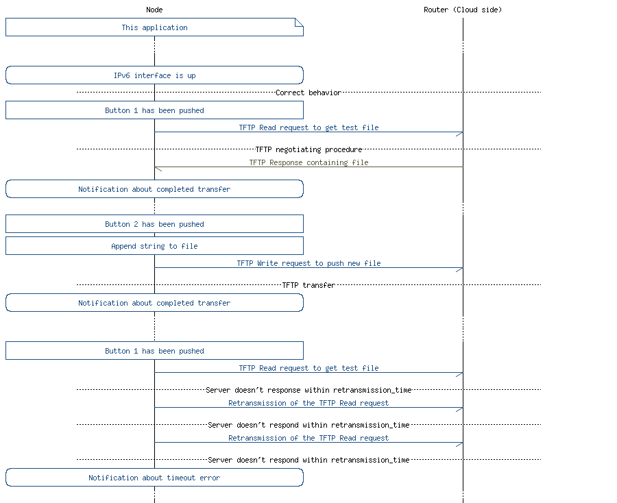
The demo setup and flow diagram are presented in Figure 1.

This example demonstrates how Nordic's IPv6 stack can be used for getting and receiving files from a TFTP server.
The application is controlled by buttons. By pressing BUTTON 1 you can download the test.txt file from the TFTP server, which fills the internal static buffer. After pressing BUTTON 2 the application will add a "Hello!" string at the end of the file and overwrite its content on the server.
The MSC below provides an overview of the data exchange in the application between the node (nRF52) and the router/cloud in two cases:
This section summarizes the usage of nRF52 resources and common modules in the examples apart from the IoT 6LoWPAN and IPv6 stack library.
| Module | Inclusion/Usage | Description |
|---|---|---|
| Timer | 2 | Two timers - IoT timer, button module and for timing TFTP retransmission mechanism. |
| Buttons | 2 | Buttons are used for performing TFTP transfers. |
| LEDs | 4 | LEDs are used to indicate the application states. See LED assignments. |
| Scheduler | No | The scheduler is used for processing stack events. |
| UART Trace | Yes | Tracing is used to show the file contents. Trace logs from the TFTP module are not enabled by default. |
The source code and project file of the example can be found at: <InstallFolder>/examples/iot/tftp/client
| Application State | LED 1 State | LED 2 State | LED 3 State | LED 4 State |
|---|---|---|---|---|
| Idle | OFF | OFF | OFF | OFF |
| Advertising | BLINKING | OFF | OFF | OFF |
| IPv6 Interface Up | OFF | ON | OFF | OFF |
| IPv6 Interface Down | ON | BLINKING | OFF | OFF |
| ASSERT | ON | ON | ON | ON |
| TFTP operation | Button number |
|---|---|
| Read file from the server | 1 |
| Append data and write file to the server | 2 |
See Connecting devices to the router for a list of relevant Linux commands.
By default the UART interface is connected with a J-Link virtual USB serial interface to your computer. In order to read from this interface:
| Property | Value |
|---|---|
| Baudrate | 1 000 000 |
| Flow control | XON/XOFF |
| Data bits | 8 bits |
| Number of stop bits | 1 bit |
| Parity | None |
 1.8.3.1
