Working with nRF53 Series
The nRF Connect SDK provides support for developing on the nRF5340 System on Chip (SoC) using the nRF5340 DK (PCA10095).
See the nRF5340 DK User Guide for detailed information about the nRF5340 DK hardware. To get started with the nRF5340 DK, follow the steps in the Getting started with nRF Connect SDK (nRF53 Series) guide.
Note
The nRF5340 PDK has been deprecated with the introduction of the production-level nRF5340 DK. To determine if you have a PDK or DK, check the version number on the sticker on your kit. If the version is 0.11.0 or higher, the kit is an nRF5340 DK.
See the nRF Connect SDK v1.4.0 documentation for the last release supporting the nRF5340 PDK.
Introduction
nRF5340 is a wireless ultra-low-power multicore System on Chip (SoC) with two fully programmable Arm Cortex-M33 processors: a network core and an application core.
See the nRF5340 Product Specification for more information about the nRF5340 SoC. nRF5340 DK gives an overview of the nRF5340 DK support in Zephyr.
Network core
The network core is an Arm Cortex-M33 processor with a reduced feature set, designed for ultra-low-power operation. Use this core for radio communication and for real-time processing tasks involving low-level radio protocol layers.
The build target for the network core in Zephyr is nrf5340dk_nrf5340_cpunet.
Application core
The application core is a full-featured Arm Cortex-M33 processor including DSP instructions and FPU. Use this core for tasks that require high performance and for application-level logic.
The M33 TrustZone divides the application MCU into secure and non-secure domains. When the MCU boots, it always starts executing from the secure area. The nRF Connect SDK provides two alternatives for running applications from the non-secure area of the memory:
- Secure Partition Manager (SPM)
The Secure Partition Manager sample uses the SPU peripheral to configure security attributions for flash, SRAM, and peripherals. After the configuration setup is complete, the sample loads the application firmware from the non-secure domain. In addition, the SPM sample can provide access to secure services to the application firmware.
The SPM sample is currently the default solution used by most nRF Connect SDK samples. This means that when you build your application for the non-secure domain, the Secure Partition Manager sample is automatically included in the build.
- Trusted Firmware-M (TF-M)
Trusted Firmware-M provides a highly configurable set of software components to create a Trusted Execution Environment. TF-M is a framework which will be extended for new functions and use cases beyond the scope of SPM.
Support for TF-M in nRF Connect SDK is currently experimental. If your application does not depend on the secure services developed in SPM and does not use them, then TF-M can replace SPM as the secure firmware component in your application.
For more information and instructions on how to do this, see Running applications with Trusted Firmware-M. See TF-M Hello World for a sample that demonstrates how to add TF-M to an application.
In Zephyr, the application core is divided into two different build targets:
nrf5340dk_nrf5340_cpuappfor the secure domainnrf5340dk_nrf5340_cpuapp_nsfor the non-secure domain
Note
In nRF Connect SDK releases before v1.6.1, the build target nrf5340dk_nrf5340_cpuapp_ns was named nrf5340dk_nrf5340_cpuappns.
Inter-core communication
Communication between the application core and the network core happens through a shared memory area. The application core memory is mapped to the network core memory map. This means that the network core can access and use the application core memory for shared memory communication.
Interprocessor Communication (IPC) is used to indicate to the other core that there is new data available to pick up. The actual data exchange is handled by Open Asymmetric Multi-Processing (OpenAMP).
Zephyr includes the OpenAMP library, which provides a complete solution for exchanging messages between the cores. The IPC peripheral is presented to Zephyr as an Interprocessor Mailbox (IPM) device. The OpenAMP library uses the IPM SHIM layer, which in turn uses the IPC driver in nrfx.
Protocols and use cases
nRF5340 samples usually consist of two separate images: one that runs on the network core and one that runs on the application core. For specific use cases, you can use only one of the cores.
The following sections describe the recommended architecture for using different protocols on the nRF5340 and list the provided samples.
Bluetooth Low Energy
Network core |
Application core |
|---|---|
Bluetooth: Host for nRF RPC Bluetooth Low Energy (supported for development) |
Some Bluetooth Low Energy samples, for example, Bluetooth: Beacon |
When using Bluetooth® Low Energy on the nRF5340, you have two options:
Split the Bluetooth LE Controller and the host part of the Bluetooth LE stack and run them on different cores.
Run the full Bluetooth LE stack on the network core (currently supported for development only).
Split Controller and Host
When splitting the Bluetooth LE Controller and the Host, run the Bluetooth LE Controller on the network core and the host part of the Bluetooth LE stack and the application logic on the application core.
For the network core, the nRF Connect SDK provides the Bluetooth: HCI RPMsg sample. This Zephyr sample is designed specifically to enable the Bluetooth LE Controller functionality on a remote MCU using the RPMsg Messaging Protocol as a transport for Bluetooth HCI. The sample implements the RPMsg transport using the OpenAMP library to communicate with a Bluetooth Host stack that runs on a separate core (in this case, the nRF5340 application core).
You can use either the SoftDevice Controller or the Zephyr Bluetooth LE Controller for this sample. See Bluetooth LE Controller for more information.
For the application core, the nRF Connect SDK provides a series of Bluetooth Low Energy samples, in addition to the Bluetooth samples in Zephyr. These samples are built for the application core and, by default, include the network core application as child image in a multi-image build (see Single image vs. multi-image build).
Note
Most of the provided Bluetooth LE samples should run on the nRF5340 DK, but not all have been thoroughly tested.
Full Bluetooth LE stack
To run the full Bluetooth LE stack on the network core, the nRF Connect SDK provides the Bluetooth: Host for nRF RPC Bluetooth Low Energy sample.
Note
The Bluetooth: Host for nRF RPC Bluetooth Low Energy sample is currently supported for development only. It does not support all Bluetooth Host APIs yet.
For the application core, use a compatible Bluetooth LE sample, for example, the Bluetooth: Beacon sample.
IEEE 802.15.4 (Thread and Zigbee)
Network core |
Application core |
|---|---|
When using IEEE 802.15.4 on the nRF5340, run the IEEE 802.15.4 radio driver on the network core and the high-level radio stack (the host part of the Thread and Zigbee stacks) and the application logic on the application core.

IEEE 802.15.4 Protocol architecture in multicore SoC
For the network core, the nRF Connect SDK provides the nRF IEEE 802.15.4: Serialization RPMsg sample. This Zephyr sample is designed specifically to enable the nRF IEEE 802.15.4 radio driver and its serialization library on a remote MCU using the RPMsg Messaging Protocol as a transport for the nRF 802.15.4 radio driver serialization. The sample implements the RPMsg transport using the OpenAMP library to communicate with the nRF IEEE 802.15.4 radio driver serialization host that runs on a separate core (in this case, the nRF5340 application core).
For the application core, the nRF Connect SDK provides a series of samples for the Thread, Zigbee, and Matter protocols. These samples are built for the application core and, by default, include the network core application as child image in a multi-image build (see Single image vs. multi-image build).
Multiprotocol (Thread or Zigbee in combination with Bluetooth LE)
Network core |
Application core |
|---|---|
nRF5340 supports running another protocol in parallel with the SoftDevice Controller. When using Thread or Zigbee in parallel with Bluetooth LE, run the low-level radio protocol layers (thus the IEEE 802.15.4 radio driver and the Bluetooth LE Controller) on the network core and the high-level radio stack (the host part of the Bluetooth LE, Thread, and Zigbee stacks) and the application logic on the application core.

Bluetooth LE and IEEE 802.15.4 multiprotocol architecture in multicore SoC
For the network core, the nRF Connect SDK provides the nRF5340: Multiprotocol RPMsg sample. It is a combination of the Bluetooth: HCI RPMsg sample (for Bluetooth LE) and the nRF IEEE 802.15.4: Serialization RPMsg sample (for IEEE 802.15.4). This means that it enables both the Bluetooth LE Controller and the nRF IEEE 802.15.4 radio driver and simultaneously exposes the functionality of both stacks to the application core using the RPMsg Messaging Protocol. Separate RPMsg endpoints are used to obtain independent inter-core connections for each stack.
For the application core, the nRF Connect SDK provides a series of samples for the Thread and Zigbee protocols. These samples are built for the application core and, by default, include the network core application as child image in a multi-image build (see Single image vs. multi-image build). See the Multiprotocol support user guide for instructions on how to enable multiprotocol support for Thread or Zigbee in combination with Bluetooth.
Direct use of the radio peripheral
Network core |
Application core |
|---|---|
Note
The above list might not be exhaustive.
Samples that directly use the radio peripheral can run on the network core of the nRF5340. They do not require any functionality from the application core.
However, on nRF5340, the application core is responsible for starting the network core and connecting its GPIO pins (see CONFIG_BOARD_ENABLE_CPUNET and the code in zephyr/boards/arm/nrf5340dk_nrf5340/nrf5340_cpunet_reset.c).
Therefore, you must always program the application core, even if the firmware is supposed to run only on the network core.
You can use the nRF5340: Empty firmware for application core sample for this purpose.
Configure the network core application to automatically include this sample as a child image.
This is the default configuration for the listed network core samples.
For more information, see CONFIG_NCS_SAMPLE_EMPTY_APP_CORE_CHILD_IMAGE and Single image vs. multi-image build.
No radio communication
Network core |
Application core |
|---|---|
— |
Note
The above list might not be exhaustive.
Samples that do not need radio communication can run on the application core of the nRF5340. They do not require any firmware on the network core. Therefore, the network core can remain empty.
If you want to enable the network core anyway, set the CONFIG_BOARD_ENABLE_CPUNET option in the image for the application core.
Single image vs. multi-image build
If a sample consists of several images (in this case, different images for the application core and for the network core), you can build these images separately or combined as a multi-image build, depending on the sample configuration.
In a multi-image build, the image for the application core is usually the parent image, and the image for the network core is treated as a child image in a separate domain. For this to work, the network core image must be explicitly added as a child image to one of the application core images. See Defining and enabling a child image for details.
Note
When using the nRF5340: Empty firmware for application core sample, the image hierarchy is inverted. In this case, the network core image is the parent image and the application core image is the child image.
Default build configuration
By default, the two images are built together for all Bluetooth LE, Thread, Zigbee, and Matter samples in the nRF Connect SDK. Samples that are designed to run only on the network core include the nRF5340: Empty firmware for application core sample as a child image. For other samples, the images are built separately.
The build configuration depends on the following Kconfig options that must be set in the configuration of the parent image:
CONFIG_BT_RPMSG_NRF53- set toyin all Bluetooth LE samples for the application coreCONFIG_NRF_802154_SER_HOST- set toyin all Thread, Zigbee, and Matter samples for the application coreCONFIG_NCS_SAMPLE_EMPTY_APP_CORE_CHILD_IMAGE- set toyin all network core samples that require the nRF5340: Empty firmware for application core sample
The combination of these options determines which (if any) sample is included in the build of the parent image:
Enabled options |
Child image sample for the network core |
Child image sample for the application core |
|---|---|---|
— |
||
— |
||
— |
||
— |
Configuration of the child image
When a network sample is built automatically as a child image in a multi-image build, you can define the relevant Kconfig options (if required) in a .conf file.
Name the file network_sample.conf, where network_sample is the name of the child image (for example, hci_rpmsg.conf).
Place the file in a child_image subfolder of the application sample directory.
See Image-specific variables for more information.
This way of defining the Kconfig options allows to align the configurations of both images.
For example, see the Bluetooth: Throughput child image configuration in nrf/samples/bluetooth/throughput/child_image/hci_rpmsg.conf.
Building and programming a sample
Depending on the sample, you must program only the application core (for example, when using NFC samples) or both the network and the application core.
The steps differ depending on whether you work with SEGGER Embedded Studio or on the command line and whether you are doing a single or multi-image build.
Using SEGGER Embedded Studio
To build and program separate images with SEGGER Embedded Studio, follow the general instructions for Building with SES. To program a multi-image HEX file, you must add the project files for the network core after building, as described in Multi-image build.
Separate images
To build and program only the application core, follow the instructions in Building with SES and use nrf5340dk_nrf5340_cpuapp or nrf5340dk_nrf5340_cpuapp_ns as build target.
To build and program a dedicated network sample, follow the instructions in Building with SES and use nrf5340dk_nrf5340_cpunet as the build target.
Multi-image build
If you are working with Bluetooth LE, Thread, Zigbee, or Matter samples, the network core sample is built as child image when you build the application core image (see Single image vs. multi-image build above).
However, SEGGER Embedded Studio cannot automatically program the network sample to the network core when it is added as a child image. You must manually add a network core project to the application core project to make sure that both are programmed.
Note
You must reprogram the network core sample only when changes are made to it. You can modify and program the application core sample without reprogramming the network core.
Follow these steps to build and program a multi-image build to the nRF5340 application core and network core:
Follow the instructions in Building with SES and open the application core sample (for example, Bluetooth: Peripheral LBS) in SEGGER Embedded Studio. Use
nrf5340dk_nrf5340_cpuappornrf5340dk_nrf5340_cpuapp_nsas the build target.Build the sample as described in Building with SES. This creates both the application core image and the network core image.
Select File > New Project.
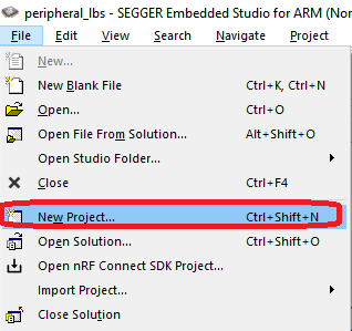
Create New Project menu
Select Add the project to the current solution.
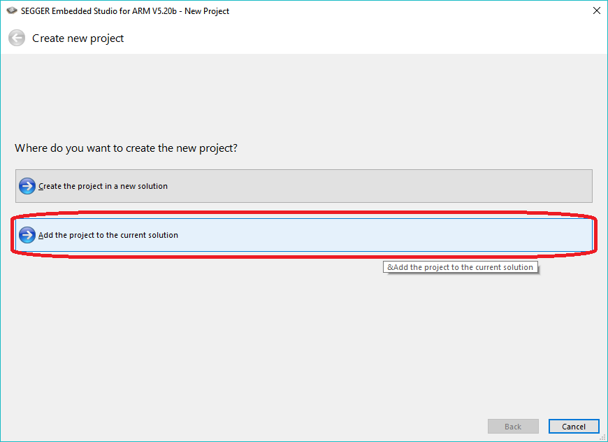
Adding a project target for programming the network core
Select the project template, project name, and project location.
An externally built executable for Nordic Semiconductor nRF: This template allows you to specify the network core HEX file to be programmed. The HEX file is created by the build system.
Name: Specify the name of the project as it will appear in SES. This example uses
hci_rpmsg_nrf5340_netcore.Location: Specify the location of the project. This must be the same location as the current project/build folder. Click Browse to open a dialog where you can navigate to the current project/build folder and click Select Folder.
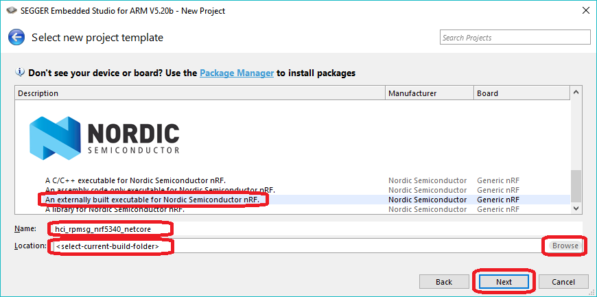
Creating a new project for programming the network core
Click Next.
Configure the project settings.
Target Processor: Select
nRF5340_xxAA_Network.Load File: Specify the file name of the merged HEX file for the network core that should be programmed. For example, specify
$(ProjectDir)/hci_rpmsg/zephyr/merged_CPUNET.hexfor the Bluetooth: HCI RPMsg sample.
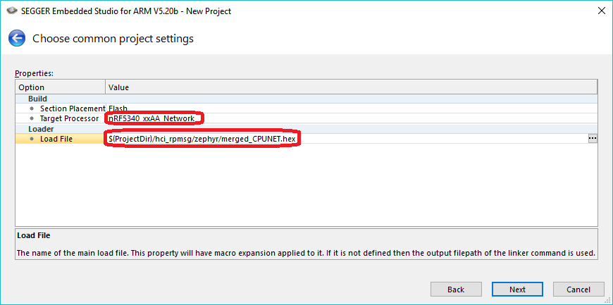
Project settings for programming the network core
Click Next.
Add the project files. This project will only be used for programming the network core so you must only add the default Script Files.
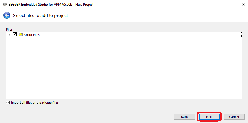
Adding script files for programming the network core
Click Next.
Add the project configurations. This project will only be used for programming the network core so no build configurations are needed.
Deselect Debug and Release.
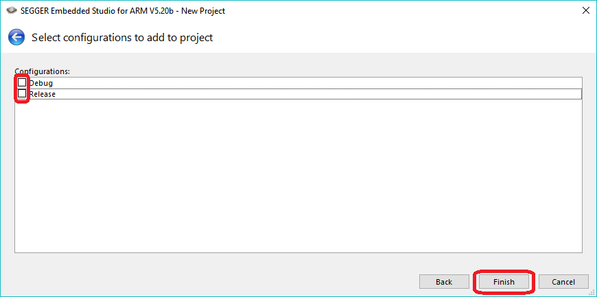
Deselecting configurations and finishing the configuration
Click Finish.
This creates a new project for programming the network core with the HEX file of the network sample.
Set the new network core project as the active project using Project > Set Active Project. For example, select hci_rpmsg_nrf5340_netcore.
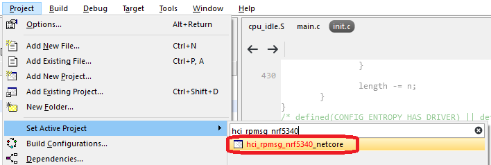
Set the hci_rpmsg_nrf5340_netcore programming target as active
Program the network sample using Target > Download XXX (for example, Download hci_rpmsg_nrf5340_netcore).
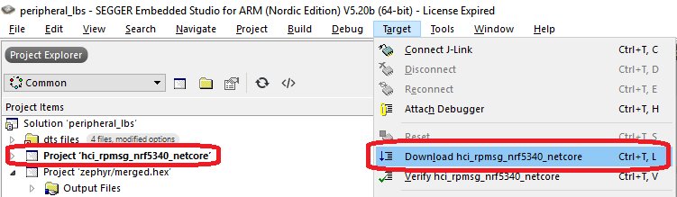
Program the network sample hci_rpmsg_nrf5340_netcore
Ignore any warnings regarding the project being out of date. The network core project is a pure programming target, so it cannot be built.
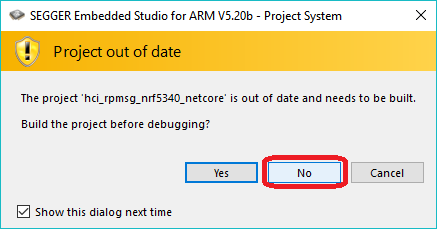
Ignore any ‘Project out of date’ warning
Note
Programming the network core erases the application.
After the network core is programmed, make the application target active again by selecting Project > Set Active Project > zephyr/merged.hex.
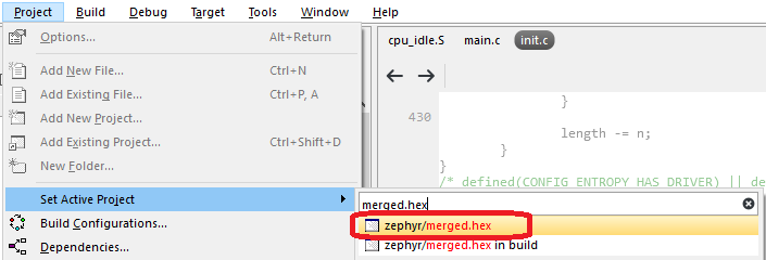
Set the zephyr/merged.hex target as active
Program the application sample using Target > Download zephyr/merged.hex.
Using the command line
To build nRF5340 samples from the command line, use west. To program the nRF5340 DK from the command line, use either west or nrfjprog (which is part of the nRF Command Line Tools).
Note
Programming the nRF5340 DK from the command line (with west or nrfjprog) requires the nRF Command Line Tools v10.12.0 or later.
Separate images
To build and program the application sample and the network sample as separate images, follow the instructions in Building on the command line for each of the samples.
See the following instructions for programming the images separately:
First, open a command prompt in the build folder of the network sample and enter the following command to erase the flash memory of the network core and program the network sample:
west flash --erase
Then navigate to the build folder of the application sample and enter the same command to erase the flash memory of the application core and program the application sample:
west flash --erase
First, open a command prompt in the build folder of the network sample and enter the following command to erase the flash memory of the network core and program the network sample:
nrfjprog -f NRF53 --coprocessor CP_NETWORK --program zephyr/zephyr.hex --chiperase
Then navigate to the build folder of the application sample and enter the following command to erase the flash memory of the application core and program the application sample:
nrfjprog -f NRF53 --program zephyr/zephyr.hex --chiperase
Finally, reset the development kit:
nrfjprog --pinreset
See Readback protection if you encounter an error.
Multi-image build
To build and program a multi-image HEX file, follow the instructions in Building on the command line for the application core sample.
To program the multi-image HEX file, you must use west. Programming multi-image builds for different cores is not yet supported in nrfjprog.
Readback protection
When programming the device, you might get an error similar to the following message:
ERROR: The operation attempted is unavailable due to readback protection in
ERROR: your device. Please use --recover to unlock the device.
This error occurs when readback protection is enabled. To disable the readback protection, you must recover your device. See the following instructions.
Enter the following command to recover both cores:
west flash --recover
Enter the following commands to recover first the network core and then the application core:
nrfjprog --recover --coprocessor CP_NETWORK
nrfjprog --recover
Note
Make sure to recover the network core before you recover the application core.
The --recover command erases the flash memory and then writes a small binary into the recovered flash memory.
This binary prevents the readback protection from enabling itself again after a pin reset or power cycle.
Recovering the network core erases the flash memory of both cores. Recovering the application core erases only the flash memory of the application core. Therefore, you must recover the network core first. Otherwise, if you recover the application core first and the network core last, the binary written to the application core is deleted and readback protection is enabled again after a reset.
FOTA upgrades
You can upgrade the firmware of the device over the air, thus without a wired connection. Such an upgrade is called a FOTA (firmware over-the-air) upgrade. FOTA upgrades can be used to replace the application.
Note
The following instructions are for the application core.
To upgrade the firmware on the network core, perform the steps for FOTA upgrade described below, replacing app_update.bin, which is the file used when upgrading firmware on the application core, with net_core_app_update.bin.
In addition, ensure that CONFIG_PCD_APP is enabled for the MCUboot child image.
For more details, see nRF5340: Network core bootloader.
To perform a FOTA upgrade, complete the following steps:
- Make sure that your application supports FOTA upgrades.
To download and apply FOTA upgrades, the following requirements apply:
You must enable the mcumgr module, which handles the transport protocol over Bluetooth Low Energy. To enable this module in your application, complete the following steps:
Enable
CONFIG_MCUMGR_CMD_OS_MGMT,CONFIG_MCUMGR_CMD_IMG_MGMT, andCONFIG_MCUMGR_SMP_BT.Call
os_mgmt_register_group()andimg_mgmt_register_group()in your application.Call
smp_bt_register()in your application to initialize the mcumgr Bluetooth Low Energy transport.
See the code of the SMP Server Sample for an implementation example. After completing these steps, your application should advertise the SMP Service with UUID 8D53DC1D-1DB7-4CD3-868B-8A527460AA84.
To upgrade the application, you must use MCUboot as the upgradable bootloader (
CONFIG_BOOTLOADER_MCUBOOTmust be enabled).
- Create a binary file that contains the new image.
To create a binary file for an application upgrade, make sure that
CONFIG_BOOTLOADER_MCUBOOTis enabled and build the application as usual. The build will create several binary files (see Using MCUboot in nRF Connect SDK). Theapp_update.binfile is the file that must be downloaded to the device.
- Download the new image to a device.
Use nRF Connect for Mobile or nRF Toolbox to upgrade your device with the new firmware.
To do so, make sure that you can access the
app_update.binfile from your phone or tablet. Then connect to the device with the mobile app and initiate the DFU process to transferapp_update.binto the device.Note
There is currently no support for the FOTA process in nRF Connect for Desktop.
Simultaneous multi-image DFU
The simultaneous update of multiple images is available for testing since nRF Connect SDK v1.7.0. It allows the updating of both the application core and the network core in one go.
To enable the simultaneous update of multiple images in the MCUboot, set the following options:
CONFIG_BOOT_UPGRADE_ONLY- The simultaneous update of multiple images does not support network core image reversion, so you need to disable application image reversion.CONFIG_PCD_APP- Enable commands exchange with the network core.CONFIG_UPDATEABLE_IMAGE_NUMBER- Enable support for multiple update partitions by setting this option to2.
To enable the simultaneous update of multiple images in the application, in addition to enabling the MCUboot support, set the following options:
CONFIG_UPDATEABLE_IMAGE_NUMBER- Enable support for multiple update partitions by setting this option to2.
Additionally, the memory partitions must be defined and include:
mcuboot_primaryandmcuboot_secondarypartitions for the application core image slots.mcuboot_primary_1andmcuboot_secondary_1partitions for the network core image slots.pcd_srampartition used for command exchange between the application core and the network core (seeCONFIG_PCD_APP).
Note
The application core does not have direct access to the network core flash memory.
The update image is passed indirectly using RAM.
Because of this, the mcuboot_primary_1 must be stored in ram_flash region.
To enable providing such region on the device, see CONFIG_FLASH_SIMULATOR.
Samples and applications built for Thingy:53 enable simultaneous update of multiple images by default. To learn more about Thingy:53, see Working with Thingy:53.
Container for firmware update binaries
The build system will automatically place both the application core and the network core update binaries (app_update.bin and net_core_app_update.bin) into a container package named dfu_application.zip.
This container package can be used by update tools to pass both images during the simultaneous update of multiple images.
Getting logging output
When connected to the computer, the nRF5340 DK emulates three virtual COM ports. In the default configuration:
Logging output from the application core sample is available on the third (last) COM port.
Logging output from the network core (if available) is routed to the first COM port.
The second (middle) COM port is silent.