nRF Pelion Client
The nRF Pelion Client application demonstrates the integration of the Pelion Device Management library within the nRF Connect SDK. The application constructs Open Mobile Alliance (OMA) objects, connects to the Pelion Device Management platform, and sends data to the web server over either LTE or OpenThread.
Pelion is an IoT cloud platform that offers services in the fields of connectivity, device management, and edge computing. It allows you to remotely manage and update your IoT devices. To read more, see the Pelion website and the Pelion Device Management documentation.
Note
The application uses Pelion’s mbed-cloud-client library, which is fetched as a module into the ncs/modules/lib/pelion-dm directory of the nRF Connect SDK.
Later on this page, this library is referred to as Pelion Device Management library.
Overview
The application integrates Pelion Device Management features and is based on the Pelion Device Management Client library reference example. It establishes a secure connection with the Pelion Device Management, starts the Pelion Device Management library, and initializes the Pelion Device Management Client. The Device Management Client creates standard OMA objects that you can interact with from Pelion Device Management Portal. It then communicates with the network using sockets.
Device provisioning
You must provision the device before it can connect with Pelion Device Management Portal.
When using Pelion, you can complete the provisioning process using either a production tool (Factory Configurator Utility for factory provisioning) or the developer flow process. For more information about the provisioning process, see Provisioning devices for Pelion Device Management in the Pelion documentation.
The application follows the developer flow provisioning process. This process involves downloading a source file that contains a valid certificate. The file is available from Pelion Device Management Portal and is used at build time to embed the required information to the application binary.
Upon first boot, or whenever the Pelion storage partition is erased (fcc_storage_delete()), the storage is populated with the credentials passed at build time.
The application does this by calling fcc_developer_flow() right after the Factory Configurator Client (FCC) is initialized (fcc_init()).
For more information about these functions, see the Pelion’s factory_configurator_client.h file reference page.
Using a valid certificate allows the device to successfully register (connect) to Pelion Device Management Portal. At this stage, the device is assigned a new device identity.
Note
Pressing and holding Button 1 during the board boot up starts the factory reset process. Triggering the factory reset starts the provisioning process again.
Run time flow overview
The following sections describe the application operational flow at run time, after provisioning:
Factory Configuration Client initialization
After the board boot sequence, the application’s pelion_fcc module initializes Pelion’s FCC.
At this stage, the developer flow is enabled and the certificate is loaded to the Pelion storage partition (if needed).
Network back end initialization
In parallel to the FCC initialization, the application initializes the network back end.
The appropriate net module connects the required callbacks and starts either OpenThread (net_ot, using Zephyr’s Thread protocol) or the link control (net_lte, using the Modem library integration layer).
The network module tracks the connection state and informs the rest of the application if the connection is established or the network is disconnected.
Pelion Device Management library initialization
The Device Management Client object is initialized from the Pelion Device Management library when the FCC is initialized. The library attaches several client callbacks that are required for informing the application about the connection status with Pelion Device Management Portal.
OMA object creation
After the Device Management Client is initialized by the application, it sends create_object_event, which starts the creation of OMA objects, object instances, and object resources for each instance.
Each module used by the application completes this operation using the Pelion Device Management library API.
The nRF Pelion Client application creates objects of two types: OMA Digital Input and OMA Stopwatch.
You can find the code for handling these in the oma_digital_input.cpp and oma_stopwatch.cpp files, respectively, located in the src/modules directory.
When all resources are created, they are added to the Device Management Client.
Pelion setup finalization
The Device Management Client uses standard network sockets for communication. To avoid unnecessary pinging to servers on the network, the client setup is performed only after the network connection is established. When information about the network back end connection is broadcast by the network module, the Pelion module continues with setting up the Device Management Client.
Network communication
The Device Management Client starts communicating with the servers, either over LTE or OpenThread. The device registers with Pelion Device Management Portal, if a valid certificate was provided at build time. Information about all resources added to the Device Management Client is passed to Pelion Device Management Portal.
This completes the run time operational flow of the device. You can now locate the device in the device directory of the Device Management and start interacting with it. See User interface and Testing sections for more information about interaction options.
Firmware architecture
To allow greater flexibility for future modifications, the application has a modular structure, where each module has a defined scope of responsibility. The application uses the Event Manager to distribute events between modules in the system.
The following table lists modules that are part of the application.
Module |
Related application events |
Comment |
|---|---|---|
|
Sends |
Brings up the Device Management Client object and interacts with it. Monitors the connection state to the Device Management Portal. |
|
Reacts to |
Initializes Pelion’s Factory Configurator Client (FCC) and initiates the developer flow mode. |
|
None. |
If enabled, it initializes debug traces in the Pelion Device Management library. |
|
Send |
Initialize the network back end and track the network connection state. |
|
Reacts to |
Registers the respective Open Mobile Alliance object resources, which work as an example of the device communication with the cloud. This resource enables buttons. When starting the board, the firmware registers four buttons in Pelion Device Management Portal. It then registers the status of the button (pushed or unpushed) and the number of pushes. |
|
Reacts to |
Registers the respective Open Mobile Alliance object resources, which work as an example of the device communication with the cloud. This resource counts time, increasing it periodically. You can configure the period and reset the time count. |
|
Sends |
Reflects the connection state onto LEDs. |
|
Sends |
Switches the device into the low power mode when no interaction is detected for a given period of time. |
|
Reacts to |
Confirms that the DFU image is working fine after the update process. |
|
Sends |
Checks if the factory reset is requested by the user. |
All modules react to module_state_event.
On top of these modules, the application uses the following modules from Common Application Framework (CAF), a set of generic modules based on the Event Manager and available to all applications in the nRF Connect SDK:
The following figure shows the application architecture. The figure visualizes relations between the Event Manager, modules, drivers, and libraries.

Relationship between modules and the Event Manager
Memory allocation
The application allocates memory dynamically for the following features:
Event Manager events - Memory for these events is allocated from Zephyr’s system heap.
Pelion Device Management library - Memory for this library is allocated from the libc heap.
Mbed TLS - Memory for this library is allocated from either the libc heap or a dedicated buffer.
Zephyr’s system heap
Zephyr contains its own memory allocation algorithm that implements heap.
To configure the heap memory size, use the CONFIG_HEAP_MEM_POOL_SIZE Kconfig option.
For more information about Zephyr’s system heap, see the Memory Heaps page in Zephyr’s documentation.
Libc heap
The Pelion Device Management library depends on the new libc. In case of targets without the memory management unit (MMU), given that the application is not running in the Userspace, the portion of RAM that remains unallocated for any other purpose is used by the libc heap.
Mbed TLS allocation buffer
The Mbed TLS library can use the libc heap for allocation.
Alternatively, it can use the dedicated allocation area (see mbedtls_memory_buffer_alloc_init in the official Mbed TLS documentation).
The Nordic Security Module variant of the Mbed TLS library allows to set such dedicated allocation buffer.
See CONFIG_MBEDTLS_ENABLE_HEAP and CONFIG_MBEDTLS_HEAP_SIZE for more details.
Flash memory layout
The partition layout on the flash memory is set by Partition Manager.
The application uses static configurations of partitions to ensure that the partition layout does not change between builds.
The pm_static_$CMAKE_BUILD_TYPE.yml file located in each board directory in the configuration directory defines the static Partition Manager configuration for the given board and build type.
See Configuration files for more information.
The following partitions are used by the project:
MCUboot - where the bootloader is located.
SPM - where Secure Partition Manager (SPM) is optionally located (on secure builds).
MCUboot primary slot - where the active application image is located.
Pelion storage - where the Pelion Device Management library stores its data.
Settings storage - where Zephyr’s settings subsystem stores data to be available between boots.
MCUboot secondary slot - where the application’s update image is stored.

Flash memory structure
External flash configuration
The Partition Manager supports partitions in external flash.
Enabling external flash is essential due to overall size of the application. The secondary application slot can reside within the external flash.
It is not recommended to use the external flash for holding settings or Pelion storage as these areas hold important or secret data.
Network back ends
The application supports the following network back ends:
LTE using the Modem library integration layer for the nRF9160 DK
OpenThread using Zephyr’s Thread protocol for the nRF52840 DK and nRF5340 DK
Transport structure
The Pelion Device Management library is solely responsible for communication with the Pelion Device Management. The registered resource data is transmitted using the LwM2M protocol based on CoAP. CoAP uses standard Zephyr’s UDP sockets.
The Device Management Client tries to connect to the server periodically when the server cannot be reached. To mitigate this when there is no network connectivity, the application pauses the Device Management Client when the network module informs about the network back end disconnection. The Device Management Client operation resumes when the network connection is restored.
Bootloader
The application uses MCUboot for booting and to perform its image update operation.
The MCUboot is capable of swapping the application images located on the secondary and primary slot. Because of this, the image is not booted directly from the secondary image slot. The MCUboot supports an external flash and the secondary image slot can be placed there if the application image is too large for the primary slot.
For more information about the MCUboot, see the MCUboot documentation.
Device firmware update
The application is updatable. The new image is transmitted to the device using the Pelion infrastructure.
You can configure the update by starting an update campaign on Pelion Device Management Portal. All devices for the given campaign receive the update image. If the update manifest attached to the image is valid, the new image is stored by the Pelion Device Management library into the MCUboot secondary application slot. When the entire image is stored, the device reboots and MCUboot completes the device update by swapping the application images. For details, see the Device Management Update guide in the Pelion documentation.
Note
Zephyr’s port of Pelion might not support the most recent update client features. The Device Management Update link points to the documentation of the version compatible with the nRF Connect SDK. For details, refer to the Pelion Device Management documentation and Pelion Device Management release notes.
Application states
The following diagram shows the application states for the connection to the network and Pelion Device Management Portal.

Application states
The internal procedures refer to situations where both connection types interact with each other:
The setup procedure takes place when the network connection is established, but the application has not yet connected to Pelion Device Management Portal.
The pause procedure takes place when the network connection is failing for a known reason.
The resume procedure takes place when the network connection is restored.
The state transitions are related to the LED behavior, as described in User interface.
User interface
The application uses buttons for updating the OMA object resource counters in Pelion Device Management Portal. It also uses LEDs to reflect the application tasks.
Buttons
The application uses the following buttons on the supported development kits:
Button 1 – Connected with the OMA Digital Input object instance 0.
Button 2 – Connected with the OMA Digital Input object instance 1.
Button 3 – Connected with the OMA Digital Input object instance 2.
Button 4 – Connected with the OMA Digital Input object instance 3.
Pressing each of these buttons updates the respective object’s state resource. Each button press is counted and the count value is reflected onto the respective object’s counter resource.
You can reset Digital Input objects’ counters by putting zero into their respective values in Pelion Device Management Portal.
Note
Pressing and holding Button 1 during the board boot up starts the factory reset process. Triggering the factory reset starts the provisioning process again.
LEDs
The application displays LED behavior that corresponds to the task performed by the application. The following table shows the LED behavior demonstrated by the application:
Status |
LED behavior |
Related application state |
|---|---|---|
Network back end disconnected |
LED1 breathing (500-ms period) |
NET_STATE_DISABLED or NET_STATE_DISCONNECTED |
Network back end connected |
LED1 solid on |
NET_STATE_CONNECTED |
Pelion connection search |
LED2 breathing (500-ms period) |
PELION_STATE_DISABLED or PELION_STATE_INITIALIZED or PELION_STATE_UNREGISTERED |
Pelion device suspended |
LED2 breathing (200-ms period) |
PELION_STATE_SUSPENDED |
Pelion connection established |
LED2 solid on |
PELION_STATE_REGISTERED |
See Application states for an overview of the application state transitions.
Requirements
The application supports the following development kits:
Hardware platforms |
PCA |
Board name |
Build target |
|---|---|---|---|
PCA10090 |
|
||
PCA10095 |
|
||
PCA10095 |
|
||
PCA10056 |
|
The nRF Pelion Client application is configured to compile and run as a non-secure application on nRF91’s and nRF5340’s Cortex-M33. Therefore, it automatically includes the Secure Partition Manager that prepares the required peripherals to be available for the application.
Pelion Device Management requirements
You need a developer account on Pelion Device Management Portal.
nRF Pelion Client build types
The nRF Pelion Client application does not use a single prj.conf file.
Configuration files are provided for different build types for each supported board.
Build types enable you to use different sets of configuration options for each board.
You can create several build type .conf files per board and select one of them when building the application.
This means that you do not have to use one prj.conf file for your project and modify it each time to fit your needs.
Before you start testing the application, you can select one of the build types supported by nRF Pelion Client application, depending on your development kit and the building method. The application supports the following build types:
ZDebug– Debug version of the application - can be used to verify if the application works correctly.ZRelease– Release version of the application - can be used to achieve better performance and reduce memory consumption.
Note
Selecting a build type is optional.
The ZDebug build type is used by default if no build type is explicitly selected.
For more information, see the Configuration files section.
Configuration
The application uses Pelion’s mbed-cloud-client library, which is fetched as a module into the ncs/modules/lib/pelion-dm directory of the nRF Connect SDK.
The Pelion Device Management library is enabled with CONFIG_PELION_CLIENT configuration option.
For the library to work, you must enable and properly configure the Mbed TLS library. To connect to Pelion Device Management Portal, the device must be provisioned with valid credentials. For the firmware update procedure to work, you must provision the device with valid update resources.
For more information about Pelion configuration options, read the Zephyr integration tutorial in the Pelion documentation.
Mbed TLS
The Pelion Device Management library is depending on a properly configured Mbed TLS library.
To simplify the development within the nRF Connect SDK, a predefined set of Mbed TLS configuration options was prepared.
Set compatible with Nordic Security Module can be enabled using CONFIG_PELION_NRF_SECURITY configuration option.
Pelion credentials
To be able to connect to Pelion Device Management Portal, you need to complete the following configuration:
Generate and download a developer certificate file from Pelion Device Management Portal. This file contains keys used for securing connection with the Pelion network.
Copy the downloaded file to
applications/pelion_client/configuration/common/, replacing the defaultmbed_cloud_dev_credentials.cfile.The file is used according to the developer flow provisioning (see Device provisioning). If the certificate is not present,
fcc_developer_flow()copies it from the developer certificate file (which is now part of the application binary).
For details steps, see the Provisioning development devices guide in the Pelion documentation.
Firmware update
You can provide the devices with the new version of the firmware image over-the-air from Pelion Device Management Portal (see Device firmware update).
Before the update, you must enable a compatible bootloader.
The Pelion Device Management library is compatible with MCUboot.
Enable it with the CONFIG_BOOTLOADER_MCUBOOT Kconfig option.
Along with the bootloader, you must also enable an image manager with the CONFIG_IMG_MANAGER and CONFIG_MCUBOOT_IMG_MANAGER Kconfig options.
When MCUboot is enabled the nRF Connect SDK build system generates the update image that can be uploaded to the secondary (update) slot.
The resulting signed file named app_update.bin can be found in the build directory.
For more information refer to Using MCUboot in nRF Connect SDK.
This image is signed with MCUboot private key.
By default, if private key is present at applications/pelion_client/configuration/$BOARD_NAME/mcuboot_private.pem it will be used for signing process.
If key is not present and configuration does not point to any specific key path, the default sample MCUBoot key will be used.
Additionally, if the application image is large, you may need to store the update image on an external flash device. In such case, enable the external flash support and correctly configure the partition layout.
The Pelion Device Management library’s update manager is enabled when you select the CONFIG_PELION_UPDATE Kconfig option.
This option enables components required for image transport and storage.
For the update campaign to be recognized and the image be accepted, you need to provision the device with the valid update resources (device unique identifiers and certificate used for update process validation).
These resources are normally stored on device at production time.
To simplify the development process, you can have the update resources created by the update manifest generation tool (see Pelion Manifest Tool in the Pelion documentation).
The generated C file must be stored to the update_default_resources.c file, located in the applications/pelion_client/configuration/common directory.
The update resources embedded into the application image are used to provision the device.
The manifest tool can further help during development as it gives a possibility to trigger an update campaign using one shell command.
Configuration files
You can find the configuration files in the applications/pelion_client/configuration directory.
For each supported build target, you can find a subdirectory that contains all configuration files for the given target.
Configuration files are provided for different nRF Pelion Client build types for each supported build target.
The build types names are replacing the ${CMAKE_BUILD_TYPE} variable in the configuration file names (for example, pm_static_ZDebug.yml).
If the given build type is not supported on the selected build target, an error message appears when Building and running.
In addition to the build types mentioned above, some build targets can provide more build types, which can be used to generate an application in a specific variant.
The selected build type impacts the configuration of all system elements that are enabled (application, bootloader, partition layout).
The following configuration files are specified for each build type:
app_$CMAKE_BUILD_TYPE.conf- Contains configuration of the application.mcuboot_$CMAKE_BUILD_TYPE.conf- Contains configuration of the bootloader.pm_static_$CMAKE_BUILD_TYPE.conf- Contains configuration of the partition layout.
Additionally, each build target directory contains the following configuration files:
mcuboot_private.pem- Private signature used for binary image signing.dts.overlay- The DTS overlay used to adjust the DTS for needs of the application (that is, enable and configure the required hardware)._deffiles - Configuration files for application modules.
Building and running
Before building and running the firmware, ensure that the Pelion Device Management is set up. Also, the device must be provisioned and configured with the credentials for the connection attempt to succeed. See Configuration for details.
The application is built the same way to any other nRF Connect SDK application or sample.
This sample can be found under applications/pelion_client in the nRF Connect SDK folder structure.
See Building and programming a sample application for information about how to build and program the application.
Note
For information about the known issues, see nRF Connect SDK’s Release notes and on the Known issues page.
Selecting a build type
Before you start testing the application, you can select one of the nRF Pelion Client build types, depending on your development kit and building method.
Selecting a build type in SES
To select the build type in SEGGER Embedded Studio:
Go to File > Open nRF Connect SDK project, select the current project, and specify the board name and build directory.
Select Extended Settings.
In the Extra CMake Build Options field, specify
-DCMAKE_BUILD_TYPE=selected_build_type. For example, forZReleaseset the following value:-DCMAKE_BUILD_TYPE=ZRelease.Do not select Clean Build Directory.
Click OK to re-open the project.
Note
You can also specify the build type in the Additional CMake Options field in Tools > Options > nRF Connect. However, the changes will only be applied after re-opening the project. Reloading the project is not sufficient.
Selecting a build type from command line
To select the build type when building the application from command line, specify the build type by adding the following parameter to the west build command:
-- -DCMAKE_BUILD_TYPE=selected_build_type
For example, you can replace the selected_build_type variable to build the ZRelease firmware for PCA20041 by running the following command in the project directory:
west build -b nrf52840dk_nrf52840 -d build_nrf52840dk_nrf52840 -- -DCMAKE_BUILD_TYPE=ZRelease
The build_nrf52840dk_nrf52840 parameter specifies the output directory for the build files.
Testing
After programming the application and all the prerequisites to your development kit, test the application by performing the following steps:
Connect the kit to the computer using a USB cable. The kit is assigned a COM port (Windows) or ttyACM device (Linux), which is visible in the Device Manager.
Connect to the development kit with a terminal emulator to observe log messages (for debug build types).
Reset the development kit.
Turn on the development kit. LED1 and LED2 start slowly breathing, which indicates the network is connecting to the Pelion Device Management. After several seconds, both LEDs stop blinking and remain turned on. This indicates that the device has established connection to the network back end and the Pelion server.
Log in to Pelion Device Management Portal.
In the left pane, select Device directory. The list of all available devices is displayed.
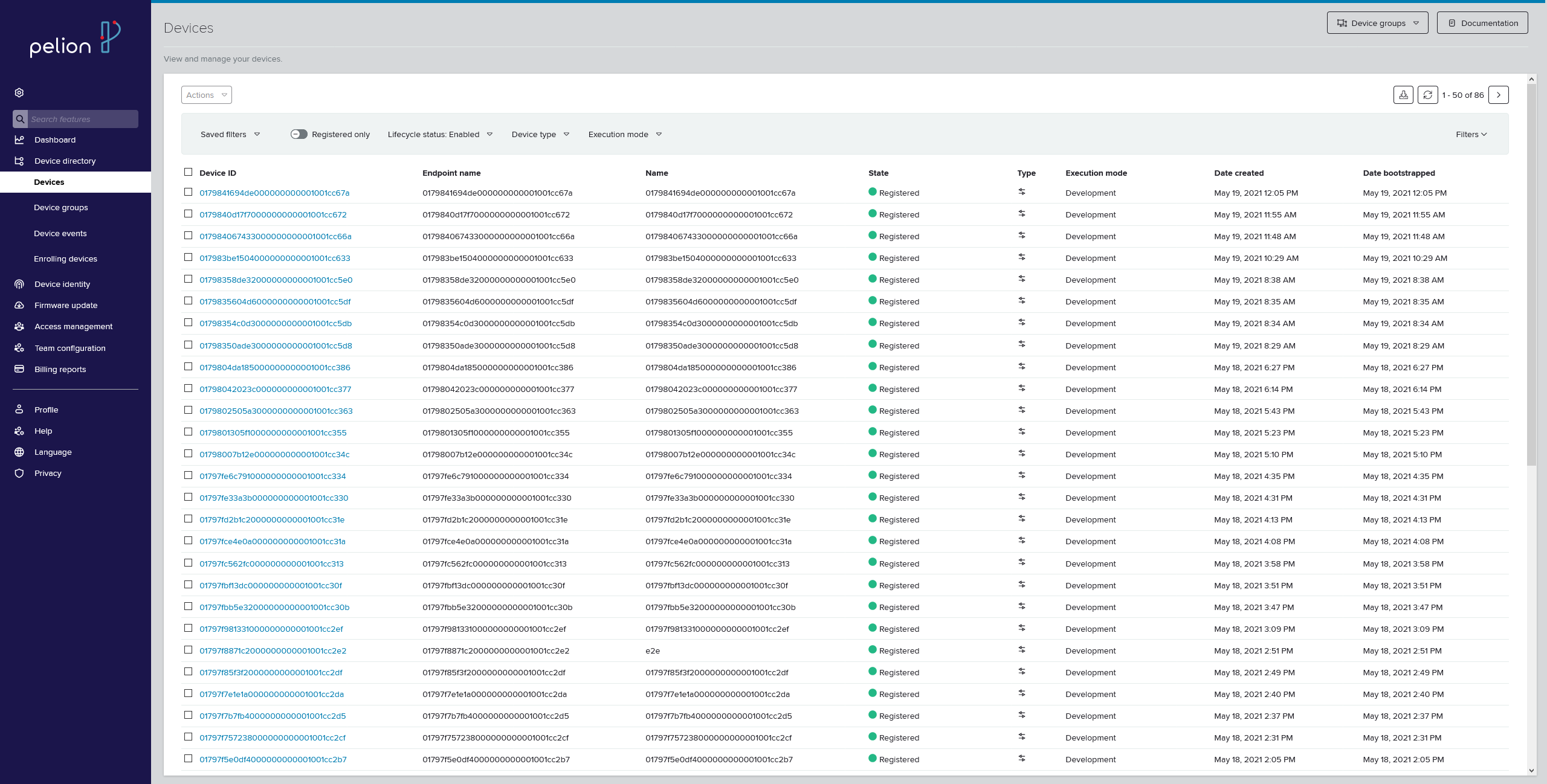
Pelion’s device directory (click to enlarge)
A device that is actively communicating with the server (or was recently communicating with it) is listed with the
Registeredstate and a green icon. The name of the device shows up on the list (and in the application log) only when it successfully connects to the server.Select your device from the list of devices. The Device details pane appears.
In the Device details pane, select the Resources tab.
Scroll down to the value for the
Digital Inputresource.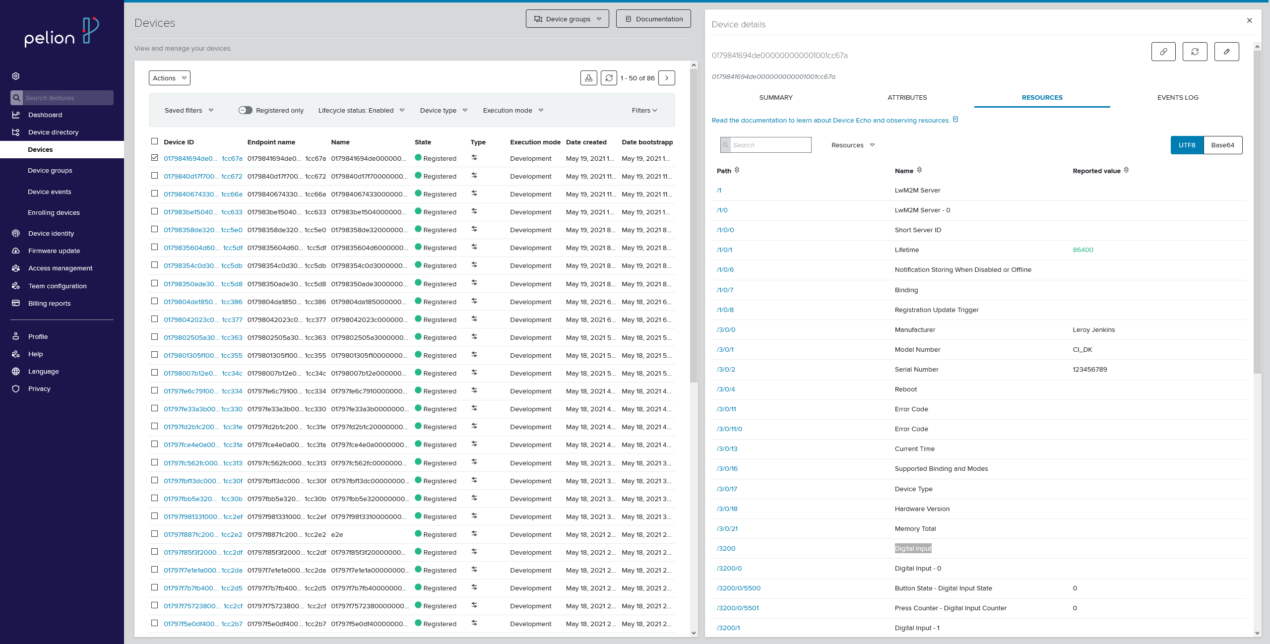
Pelion’s device directory with the resources tab selected (click to enlarge)
Press Button 1. The Digital Input instance 0 value in Pelion Device Management Portal increases.
Scroll down to the value for the
Stopwatchresource.Wait for a couple of seconds to see the value increase.
Dependencies
This application uses the following Zephyr library:
This application uses the following nRF Connect SDK libraries and drivers:
It uses the following sdk-nrfxlib libraries:
It uses the following sdk-mcuboot library:
In addition, it uses the following sample: