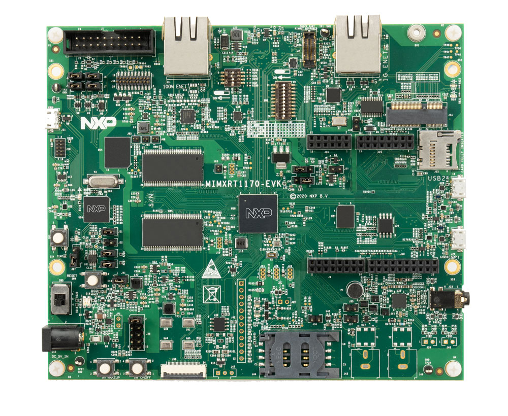
NXP MIMXRT1170-EVK
Overview
The dual core i.MX RT1170 runs on the Cortex-M7 core at 1 GHz and on the Cortex-M4 at 400 MHz. The i.MX RT1170 MCU offers support over a wide temperature range and is qualified for consumer, industrial and automotive markets.
Hardware
MIMXRT1176DVMAA MCU
1GHz Cortex-M7 & 400Mhz Cortex-M4
2MB SRAM with 512KB of TCM for Cortex-M7 and 256KB of TCM for Cortex-M4
Memory
512 Mbit SDRAM
128 Mbit QSPI Flash
512 Mbit Octal Flash
2 Gbit raw NAND flash
64 Mbit LPSPI flash
TF socket for SD card
Display
MIPI LCD connector
Ethernet
10/100 Mbit/s Ethernet PHY
10/100/1000 Mbit/s Ethernet PHY
USB
USB 2.0 OTG connector
USB 2.0 host connector
Audio
3.5 mm audio stereo headphone jack
Board-mounted microphone
Left and right speaker out connectors
Power
5 V DC jack
Debug
JTAG 20-pin connector
OpenSDA with DAPLink
Sensor
FXOS8700CQ 6-axis e-compass
MIPI camera sensor connector
Expansion port
Arduino interface
CAN bus connector
For more information about the MIMXRT1170 SoC and MIMXRT1170-EVK board, see these references:
Supported Features
The mimxrt1170_evk board configuration supports the following hardware features:
Interface |
Controller |
Driver/Component |
|---|---|---|
NVIC |
on-chip |
nested vector interrupt controller |
SYSTICK |
on-chip |
systick |
GPIO |
on-chip |
gpio |
COUNTER |
on-chip |
counter |
CAN |
on-chip |
flexcan |
SPI |
on-chip |
spi |
I2C |
on-chip |
i2c |
PWM |
on-chip |
pwm |
ADC |
on-chip |
adc |
UART |
on-chip |
serial port-polling; serial port-interrupt |
DMA |
on-chip |
dma |
GPT |
on-chip |
gpt |
WATCHDOG |
on-chip |
watchdog |
ENET |
on-chip |
ethernet |
SAI |
on-chip |
i2s |
USB |
on-chip |
USB Device |
HWINFO |
on-chip |
Unique device serial number |
DISPLAY |
on-chip |
display |
ACMP |
on-chip |
analog comparator |
The default configuration can be found in the defconfig file:
boards/arm/mimxrt1170_evk/mimxrt1170_evk_cm7_defconfig
Other hardware features are not currently supported by the port.
Connections and I/Os
The MIMXRT1170 SoC has six pairs of pinmux/gpio controllers.
Name |
Function |
Usage |
WAKEUP |
GPIO |
SW7 |
GPIO_AD_04 |
GPIO |
LED |
GPIO_AD_24 |
LPUART1_TX |
UART Console |
GPIO_AD_25 |
LPUART1_RX |
UART Console |
GPIO_LPSR_00 |
CAN3_TX |
flexcan |
GPIO_LPSR_01 |
CAN3_RX |
flexcan |
GPIO_AD_29 |
SPI1_CS0 |
spi |
GPIO_AD_28 |
SPI1_CLK |
spi |
GPIO_AD_30 |
SPI1_SDO |
spi |
GPIO_AD_31 |
SPI1_SDI |
spi |
GPIO_AD_08 |
LPI2C1_SCL |
i2c |
GPIO_AD_09 |
LPI2C1_SDA |
i2c |
GPIO_LPSR_05 |
LPI2C5_SCL |
i2c |
GPIO_LPSR_04 |
LPI2C5_SDA |
i2c |
GPIO_AD_04 |
FLEXPWM1_PWM2 |
pwm |
GPIO_AD_32 |
ENET_MDC |
Ethernet |
GPIO_AD_33 |
ENET_MDIO |
Ethernet |
GPIO_DISP_B2_02 |
ENET_TX_DATA00 |
Ethernet |
GPIO_DISP_B2_03 |
ENET_TX_DATA01 |
Ethernet |
GPIO_DISP_B2_04 |
ENET_TX_EN |
Ethernet |
GPIO_DISP_B2_05 |
ENET_REF_CLK |
Ethernet |
GPIO_DISP_B2_06 |
ENET_RX_DATA00 |
Ethernet |
GPIO_DISP_B2_07 |
ENET_RX_DATA01 |
Ethernet |
GPIO_DISP_B2_08 |
ENET_RX_EN |
Ethernet |
GPIO_DISP_B2_09 |
ENET_RX_ER |
Ethernet |
GPIO_AD_17_SAI1_MCLK |
SAI_MCLK |
SAI |
GPIO_AD_21_SAI1_TX_DATA00 |
SAI1_TX_DATA |
SAI |
GPIO_AD_22_SAI1_TX_BCLK |
SAI1_TX_BCLK |
SAI |
GPIO_AD_23_SAI1_TX_SYNC |
SAI1_TX_SYNC |
SAI |
GPIO_AD_17_SAI1_MCLK |
SAI1_MCLK |
SAI |
GPIO_AD_20_SAI1_RX_DATA00 |
SAI1_RX_DATA00 |
SAI |
System Clock
The MIMXRT1170 SoC is configured to use the 32 KHz low frequency oscillator on the board as a source for the GPT timer to generate a system clock.
Serial Port
The MIMXRT1170 SoC has 12 UARTs. One is configured for the console and the remaining are not used.
Programming and Debugging
Build and flash applications as usual (see Building an Application and Run an Application for more details).
Configuring a Debug Probe
A debug probe is used for both flashing and debugging the board. This board is configured by default to use the OpenSDA DAPLink Onboard Debug Probe, however the pyOCD Debug Host Tools do not yet support programming the external flashes on this board so you must reconfigure the board for one of the following debug probes instead.
J-Link External Debug Probe
Install the J-Link Debug Host Tools and make sure they are in your search path.
Attach a J-Link 20-pin connector to J1. Check that jumpers J6 and J7 are off (they are on by default when boards ship from the factory) to ensure SWD signals are disconnected from the OpenSDA microcontroller.
Configuring a Console
Regardless of your choice in debug probe, we will use the OpenSDA microcontroller as a usb-to-serial adapter for the serial console. Check that jumpers J5 and J8 are on (they are on by default when boards ship from the factory) to connect UART signals to the OpenSDA microcontroller.
Connect a USB cable from your PC to J11.
Use the following settings with your serial terminal of choice (minicom, putty, etc.):
Speed: 115200
Data: 8 bits
Parity: None
Stop bits: 1
Flashing
Here is an example for the Hello World application.
Before power on the board, make sure SW1 is set to 0001b
# From the root of the zephyr repository
west build -b mimxrt1170_evk_cm7 samples/hello_world
west flash
Power off the board, and change SW1 to 0010b. Then power on the board and open a serial terminal, reset the board (press the SW4 button), and you should see the following message in the terminal:
***** Booting Zephyr OS v2.4.0-xxxx-xxxxxxxxxxxxx *****
Hello World! mimxrt1170_evk_cm7
Debugging
Here is an example for the Hello World application.
# From the root of the zephyr repository
west build -b mimxrt1170_evk_cm7 samples/hello_world
west debug
Open a serial terminal, step through the application in your debugger, and you should see the following message in the terminal:
***** Booting Zephyr OS v2.4.0-xxxx-xxxxxxxxxxxxx *****
Hello World! mimxrt1170_evk_cm7