Using FEM power models
When a protocol driver requests a given transmission power to be output, MPSL splits the power into the following components: the SoC Power and the FEM gain. This gain is considered constant and accurate even if external conditions, such as temperature, might affect the effective gain achieved by the Front-End Module.
To perform the split differently (for example, to compensate for external conditions), you can use a FEM power model, either using one of the built-in ones or providing your own custom model.
To use FEM power models, set the CONFIG_MPSL_FEM_POWER_MODEL Kconfig option to y and either select one of the built-in models or provide a custom model, as described in the following chapters.
Note
In case of nRF21540 GPIO+SPI, the Using nRF21540 GPIO+SPI built-in power model is enabled by default.
Using nRF21540 GPIO+SPI built-in power model
The nRF21540 GPIO+SPI built-in power model attempts to keep the nRF21540’s gain constant and as close to the currently selected value of gain as possible. The model compensates varying external conditions, which results in the nRF21540 gain being independent of their changes.
Note
Only the factory-precalibrated values of gain represented by the default values of CONFIG_MPSL_FEM_NRF21540_TX_GAIN_DB_POUTA and CONFIG_MPSL_FEM_NRF21540_TX_GAIN_DB_POUTB are supported.
There are no guarantees on the correctness of the model if applied to compensate external conditions for other values of gain.
The nRF21540 built-in power model compensates for the following external conditions:
Temperature
FEM supply voltage
Carrier frequency
FEM input power.
The model assumes that the FEM supply voltage is constant.
To provide the value of this voltage to the MPSL subsystem, use the supply-voltage-mv property of nRF21540 devicetree node.
This model is enabled by default, provided that nRF21540 GPIO+SPI is enabled and selected. To enable and select nRF21540 GPIO+SPI, see Enabling GPIO+SPI mode support for nRF21540.
Although the built-in model significantly improves the performance of nRF21540 in varying external conditions, in certain scenarios you might want to disable it, for example, to save memory.
To disable the model and the resulting compensation, set CONFIG_MPSL_FEM_POWER_MODEL to n.
The figures below summarize the performance improvement of the nRF21540 when the built-in model is used. The data points in the figures are results of nRF21540 gain measurements performed in controlled, laboratory conditions. Each of the figures compares the gain achieved by a nRF21540 device in two cases: when the built-in model is used to control the nRF21540 gain settings, and when the model is disabled. All the external conditions the model compensates for, like temperature, supply voltage, carrier frequency, and input power, are presented in the figures.
The figures are divided into three groups, each of the group representing performance improvement over frequency and one other external condition for the two factory-precalibrated values of gain.
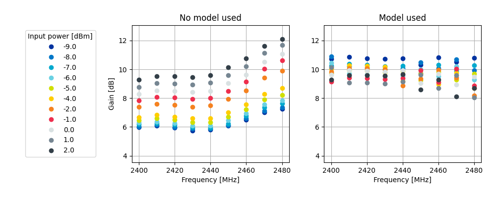
Figure 1a. nRF21540 gain vs input power over frequency sweep for 10dB setting
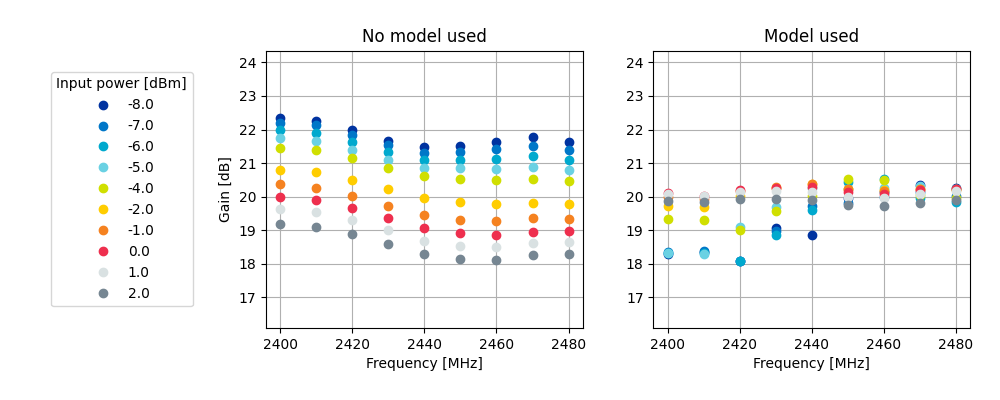
Figure 1b. nRF21540 gain vs input power over frequency sweep for 20dB setting
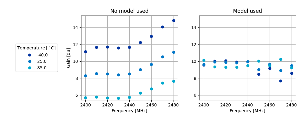
Figure 2a. nRF21540 gain vs temperature over frequency sweep for 10dB setting
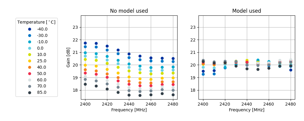
Figure 2b. nRF21540 gain vs temperature over frequency sweep for 20dB setting
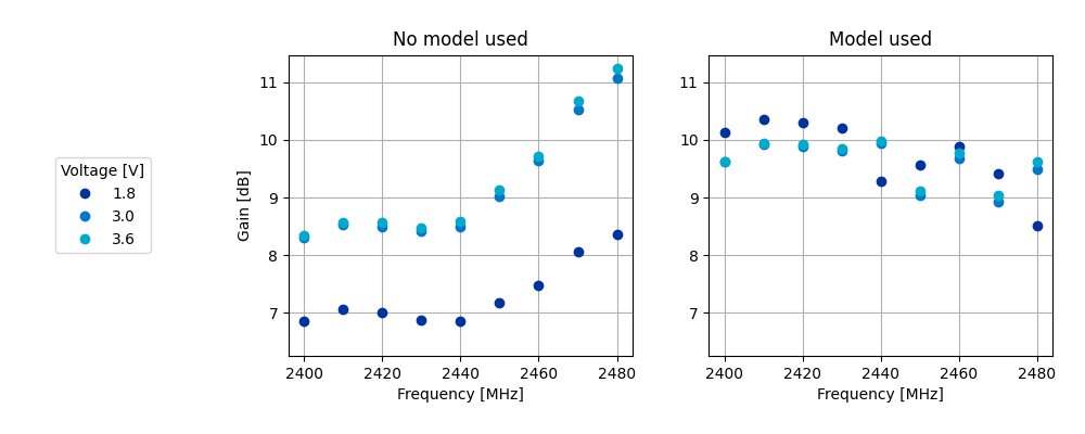
Figure 3a. nRF21540 gain vs supply voltage over frequency sweep for 10dB setting
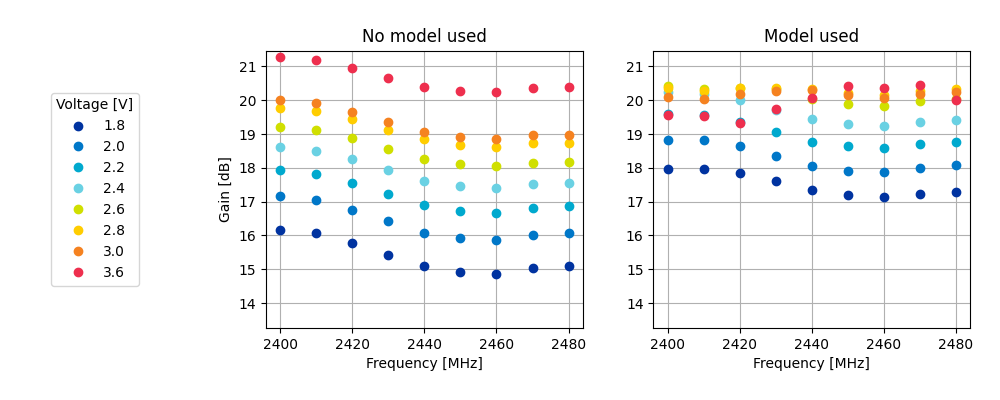
Figure 3b. nRF21540 gain vs supply voltage over frequency sweep for 20dB setting
Adding custom power models
If the way MPSL splits the TX power into components does not meet your requirements, or if you wish to implement a custom compensation model, you can provide one as follows:
Set
CONFIG_MPSL_FEM_POWER_MODELtoy.Provide an implementation of the
mpsl_fem_power_model_to_use_get()function. This function should return a pointer to a variable of the typempsl_fem_power_model_twhich contains pointers to the model’s callbacks.Mandatorily implement the model’s
fetchcallback (details explained below).Optionally implement the model’s
initcallback (details explained below). If noinitcallback is provided, passNULLas the pointer to the callback.You can also optionally extend the
MPSL_FEM_POWER_MODEL_CHOICEKconfig choice with an option to select your custom model, for example, if you want to test multiple custom models.
The init callback is called by MPSL once, after FEM configuration finishes.
Calibration data (acquired from FEM internal registers, Kconfig options, and devicetree files) is passed to this function using a parameter of the mpsl_fem_calibration_data_t type.
The meaning of the calibration data stored in this parameter is implementation-specific.
For details, see the mpsl_fem_calibration_data_t type documentation.
The fetch callback is used to split the power between the SoC output power and the FEM gain.
It is called every time this split needs to be recalculated.
For 802.15.4, this happens before every transmission.
For Bluetooth® Low Energy, this happens every time the channel changes.
Note
This function is called in a time-critical path.
Please refer to the documentation of mpsl_fem_power_model_t on timing constraints.
Any complex calculations have to be done outside this function (for example, using a look up table).
Failing to meet the timing requirements will lead to an undefined behavior of the protocol stacks.
The fetch callback must fill out all the fields of the p_output output parameter.
For more details, see the mpsl_fem_power_model_output_t type documentation.
Note
The soc_power field value must be one of the output power values supported by the given nRF SoC, otherwise the behavior is undefined.
The user can meet this requirement by converting the requested SoC power using the mpsl_tx_power_radio_supported_power_adjust function.