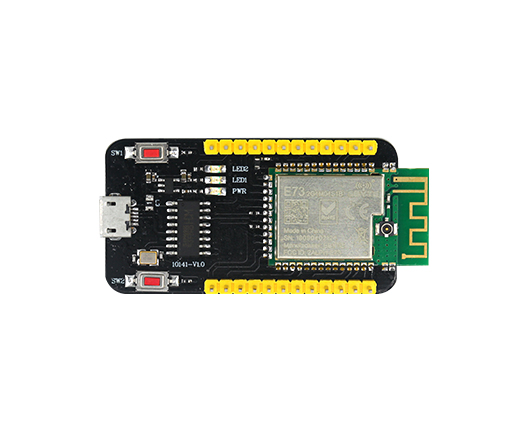
EBYTE E73-TBB
Overview
The EBYTE E73-TBB hardware provides support for the Nordic Semiconductor nRF52832 ARM Cortex-M4F CPU and the following devices:
ADC
CLOCK
FLASH
GPIO
I2C
MPU
NVIC
PWM
RADIO (Bluetooth Low Energy)
RTC
Segger RTT (RTT Console)
SPI
UART
WDT

Fig. 99 EBYTE E73-TBB (Credit: EBYTE)
More information about the board can be found at the E73-TBB website 1. The Nordic Semiconductor Infocenter 2 contains the processor’s information and the datasheet.
Hardware
E73-TBB has two external oscillators. The frequency of the slow clock is 32.768 kHz. The frequency of the main clock is 32 MHz. Additionally the board features CH340 USB-UART converter. It is possible to connect external BT antenna using U.FL socket and solder NFC antenna using NFC_ANT connector.
Supported Features
The ebyte_e73_tbb_nrf52832 board configuration supports the following hardware features:
Interface |
Controller |
Driver/Component |
|---|---|---|
ADC |
on-chip |
adc |
CLOCK |
on-chip |
clock_control |
FLASH |
on-chip |
flash |
GPIO |
on-chip |
gpio |
I2C(M) |
on-chip |
i2c |
MPU |
on-chip |
arch/arm |
NVIC |
on-chip |
arch/arm |
PWM |
on-chip |
pwm |
RADIO |
on-chip |
Bluetooth |
RTC |
on-chip |
system clock |
RTT |
Segger |
console |
SPI(M/S) |
on-chip |
spi |
UART |
on-chip |
serial |
WDT |
on-chip |
watchdog |
Other hardware features are not supported by the Zephyr kernel. See E73-TBB website 1 and Nordic Semiconductor Infocenter 2 for a complete list of nRF52832 hardware features.
Connections and IOs
LED
LED0 (red) = P0.17
LED1 (red) = P0.18
External Connectors
P1 Header
PIN # |
Signal Name |
|---|---|
1 |
GND |
2 |
3.3V |
3 |
P0.04 |
4 |
P0.03 |
5 |
P0.02 |
6 |
P0.31 |
7 |
P0.30 |
8 |
P0.29 |
9 |
P0.28 |
10 |
P0.27 |
11 |
P0.26 |
12 |
P0.25 |
P2 Header
PIN # |
Signal Name |
|---|---|
1 |
P0.24 |
2 |
P0.23 |
3 |
P0.22 |
4 |
SWDIO |
5 |
SWDCLK |
6 |
P0.21/RST |
7 |
P0.20 |
8 |
P0.19 |
9 |
P0.16 |
10 |
P0.15 |
11 |
P0.12 |
12 |
P0.11 |
NFC_ANT
PIN # |
Signal Name |
|---|---|
1 |
P0.10 |
2 |
P0.09 |
Programming and Debugging
Flashing
Follow the instructions in the Nordic nRF5x Segger J-Link page to install and configure all the necessary software. To flash the board connect pins: SWDIO, SWDCLK, RST, GND from E73-TBB to corresponding pins on your J-Link device, then build and flash the application in the usual way.
# From the root of the zephyr repository
west build -b ebyte_e73_tbb_nrf52832 samples/blinky
west flash
Debugging
Refer to the Nordic nRF5x Segger J-Link page to learn about debugging Nordic chips with a Segger IC.
