Working with RF front-end modules
An RF front-end module (FEM) is a device that amplifies the RF signal, and therefore, increases the range distance and the strength of a link’s connection. In addition to extending the range, an RF FEM also increases the robustness of the link connection. A more robust link leads to less packet loss, meaning less retransmissions. The probability of successfully receiving the first packet also increases, resulting in low link latency.
FEMs provide a power amplifier (PA) that increases the TX power and a low-noise amplifier (LNA) that increases the RX sensitivity. Some FEMs, like the nRF21540, provide a power down (PDN) control that powers down the FEM internal circuits, to reduce energy consumption.
For testing purposes, a FEM is usually integrated in either a development kit or a shield that you connect to a development kit.
This guide describes how to add support for 2 different front-end module (FEM) implementations to your application in nRF Connect SDK.
Software support
If your application uses radio protocols and requires FEM, you can enable Front-end module feature in the Multiprotocol Service Layer (MPSL) library. The test samples in nRF Connect SDK: Radio test and Bluetooth: Direct Test Mode also support FEM control. You can also use your own FEM driver when required.
Using MPSL
The MPSL library provides an implementation for the 3-pin GPIO interface of the nRF21540 and a simplified version for FEMs with a 2-pin interface. To use this implementation, your application must use a protocol driver that enables the FEM feature. The library provides multiprotocol support, but you can also use it in applications that require only one protocol. To avoid conflicts, check the protocol documentation to see if the protocol uses FEM support provided by MPSL.
The implementations supported by the MPSL library are the following:
GPIO mode - For the nRF21540 GPIO implementation that uses nRF21540.
Adding support for Skyworks front-end module - For the Simple GPIO implementation that uses the SKY66112-11 device.
Note
Currently, the following protocols use FEM support provided by MPSL:
Enabling FEM and MPSL
Before you add the devicetree node in your application, complete the following steps:
Add support for the MPSL library in your application. The MPSL library provides API to configure FEM. See Integration notes in the nrfxlib documentation for details.
Enable support for MPSL implementation in nRF Connect SDK by setting the
CONFIG_MPSLKconfig option toy.
Direct support
If your application cannot use MPSL or if the FEM driver in MPSL does not support all features you need, you can implement your own driver for nRF21540. The following samples have direct FEM support:
The implementations supported by the samples are the following:
SPI/GPIO mode - For the nRF21540 SPI/GPIO implementation that uses nRF21540.
Adding support for Skyworks front-end module - For the Simple GPIO implementation that uses the Skyworks devices.
Note
The nRF5340 DK network core peripherals, like UART and SPI, share an ID and a base address. To configure the nRF21540 front-end module gain, write the gain value over the SPI. In samples, UART is used as a control interface or shell transport. To send the gain value, UART is temporary disabled and restarted after the SPI transfer.
See the Bluetooth: Direct Test Mode samples for an example implementation.
Hardware description
The nRF Connect SDK provides a wrapper that configures FEM based on devicetree (DTS) and Kconfig information.
To enable FEM support, you must add an nrf_radio_fem node in the devicetree file.
The node can also be provided by the devicetree file of the target development kit or by an overlay file.
See Devicetree Guide for more information about the DTS data structure, and Devicetree versus Kconfig for information about differences between DTS and Kconfig.
Adding support for nRF21540
The nRF21540 device is a range extender that you can use with nRF52 and nRF53 Series devices. For more information about nRF21540, see the nRF21540 documentation.
GPIO mode
The nRF21540 GPIO mode implementation of FEM is compatible with this device and implements the 3-pin PA/LNA interface.
Note
In the naming convention used in the API of the MPSL library, the functionalities designated as PA and LNA apply to the tx-en-gpios and rx-en-gpios pins listed below, respectively.
To use nRF21540 in GPIO mode, complete the following steps:
Add the following node in the devicetree file:
/ {
      nrf_radio_fem: name_of_fem_node {
         compatible  = "nordic,nrf21540-fem";
         tx-en-gpios = <&gpio0 13 GPIO_ACTIVE_HIGH>;
         rx-en-gpios = <&gpio0 14 GPIO_ACTIVE_HIGH>;
         pdn-gpios   = <&gpio0 15 GPIO_ACTIVE_HIGH>;
   };
};
Optionally replace the node name
name_of_fem_node.Replace the pin numbers provided for each of the required properties:
tx-en-gpios- GPIO characteristic of the device that controls theTX_ENsignal of nRF21540.rx-en-gpios- GPIO characteristic of the device that controls theRX_ENsignal of nRF21540.pdn-gpios- GPIO characteristic of the device that controls thePDNsignal of nRF21540.
These properties correspond to
TX_EN,RX_EN, andPDNpins of nRF21540 that are supported by software FEM.Type
phandle-arrayis used here, which is common in Zephyr’s devicetree to describe GPIO signals. The first element&gpio0refers to the GPIO port (“port 0” has been selected in the example shown). The second element is the pin number on that port. The last element must beGPIO_ACTIVE_HIGHfor nRF21540, but for a different FEM module you can useGPIO_ACTIVE_LOW.The state of the remaining control pins should be set in other ways and according to nRF21540 Product Specification.
On nRF53 devices, you must also apply the same devicetree node mentioned in step 1 to the network core. To do so, apply the overlay to the correct network core child image by creating an overlay file named
child_image/*childImageName*.overlayin your application directory, for examplechild_image/multiprotocol_rpmsg.overlay.The
*childImageName*string must be one of the following values:multiprotocol_rpmsgfor multiprotocol applications having support for both 802.15.4 and Bluetooth.802154_rpmsgfor applications having support for 802.15.4, but not for Bluetooth.hci_rpmsgfor application having support for Bluetooth, but not for 802.15.4.
Note
This step is not needed when testing with Bluetooth: Direct Test Mode and Radio test on the nRF53 Series devices.
SPI/GPIO mode
The nRF21540 features an SPI interface. You can use it to fully control your front-end module or you can use a combination of SPI and GPIO interface. The SPI interface enables you, for example, to set the output power of the nRF21540.
To use nRF21540 in SPI or mixed mode, complete the following steps:
Add the following node in the devicetree file:
/ {
      nrf_radio_fem: name_of_fem_node {
         compatible  = "nordic,nrf21540-fem";
         tx-en-gpios = <&gpio0 13 GPIO_ACTIVE_HIGH>;
         rx-en-gpios = <&gpio0 14 GPIO_ACTIVE_HIGH>;
         pdn-gpios   = <&gpio0 15 GPIO_ACTIVE_HIGH>;
         spi-if = <&nrf_radio_fem_spi>
   };
};
Optionally replace the SPI bus device name
nrf_radio_fem_spi.Replace the pin numbers provided for each of the required properties:
tx-en-gpios- GPIO characteristic of the device that controls theTX_ENsignal of nRF21540.rx-en-gpios- GPIO characteristic of the device that controls theRX_ENsignal of nRF21540.pdn-gpios- GPIO characteristic of the device that controls thePDNsignal of nRF21540.
These properties correspond to
TX_EN,RX_EN, andPDNpins of nRF21540 that are supported by software FEM.The``phandle-array`` type is commonly used for describing GPIO signals in Zephyr’s devicetree. The first element
&gpio0refers to the GPIO port (“port 0” has been selected in the example shown). The second element is the pin number on that port. The last element must beGPIO_ACTIVE_HIGHfor nRF21540, but for a different FEM module you can useGPIO_ACTIVE_LOW.Set the state of the remaining control pins according to the nRF21540 Product Specification.
Add a following SPI bus device node on the devicetree file:
fem_spi: &spi3 {
        status = "okay";
        sck-pin = <47>;
        miso-pin = <46>;
        mosi-pin = <45>;
        cs-gpios = <&gpio0 21 GPIO_ACTIVE_LOW>;

        nrf_radio_fem_spi: nrf21540_fem_spi@0 {
                compatible = "nordic,nrf21540-fem-spi";
                status = "okay";
                reg = <0>;
                label = "FEM_SPI_IF";
                spi-max-frequency = <8000000>;
        };
};
In this example, the nRF21540 is controlled by the
spi3bus. Replace the SPI bus according to your hardware design. Replace the SPI bus device namenrf_radio_fem_spiwith the name from the previous step.Replace the pin numbers provided for each of the required properties:
sck-pin- GPIO pin number of the device that controls theSCKsignal of the nRF21540.miso-pin- GPIO pin number of the device that controls theMISOsignal of the nRF21540.mosi-pin- GPIO pin number of the device that controls theMOSIsignal of the nRF21540.cs-gpio- GPIO characteristic of the device that controls theCSNsignal of nRF21540.
sck-pin,miso-pin,mosi-pinare absolute pin numbers. Use the following formula to calculate them:pin_no = b\*32 + a
In this formula
ais a pin number andbis a port number (Pb.a). For example, for P0.1,pin_no = 1and for P1.0,pin_no = 32.
Optional properties
The following properties are optional and you can add them to the devicetree node if needed.
Properties that control the other pins:
ant-sel-gpios- GPIO characteristic of the device that controls theANT_SELsignal of nRF21540.mode-gpios- GPIO characteristic of the device that controls theMODEsignal of nRF21540.
Properties that control the timing of interface signals:
tx-en-settle-time-us- Minimal time interval between asserting theTX_ENsignal and starting the radio transmission, in microseconds.rx-en-settle-time-us- Minimal time interval between asserting theRX_ENsignal and starting the radio transmission, in microseconds.Important
Values for these two properties cannot be higher than the Radio Ramp-Up time defined by
TX_RAMP_UP_TIMEandRX_RAMP_UP_TIME. If the value is too high, the radio driver will not work properly and will not control FEM. Moreover, setting a value that is lower than the default value can cause disturbances in the radio transmission, because FEM may be triggered too late.pdn-settle-time-us- Time interval before the PA or LNA activation reserved for the FEM ramp-up, in microseconds.trx-hold-time-us- Time interval for which the FEM is kept powered up after the event that triggers the PDN deactivation, in microseconds.
The default values of these properties are appropriate for default hardware and most use cases. You can override them if you need additional capacitors, for example when using custom hardware. In such cases, add the property name under the required properties in the devicetree node and set a new custom value.
Note
These values have some constraints. For details, see nRF21540 Product Specification.
Adding support for Skyworks front-end module
You can use the Skyworks range extenders with nRF52 and nRF53 Series devices. SKY66112-11 is one of many FEM devices that support the 2-pin PA/LNA interface. The nRF Connect SDK provides also devicetree bindings for the SKY66114-11 and SKY66403-11. You can use SKY66112-11 as an example on how to create bindings for different devices that support the 2-pin PA/LNA interface. For more details about devicetree binding, see: Zephyr documentation.
Note
In the naming convention used in the API of the MPSL library, the functionalities designated as PA and LNA apply to the ctx-gpios and crx-gpios pins listed below, respectively.
To use the Simple GPIO implementation of FEM with SKY66112-11, complete the following steps:
Add the following node in the devicetree file:
/ {
   nrf_radio_fem: name_of_fem_node {
      compatible = "skyworks,sky66112-11", "generic-fem-two-ctrl-pins";
      ctx-gpios = <&gpio0 13 GPIO_ACTIVE_HIGH>;
      crx-gpios = <&gpio0 14 GPIO_ACTIVE_HIGH>;
   };
};
Optionally replace the node name
name_of_fem_node.Replace the pin numbers provided for each of the required properties:
ctx-gpios- GPIO characteristic of the device that controls theCTXsignal of SKY66112-11.crx-gpios- GPIO characteristic of the device that controls theCRXsignal of SKY66112-11.
These properties correspond to
CTXandCRXpins of SKY66112-11 that are supported by software FEM.Type
phandle-arrayis used here, which is common in Zephyr’s devicetree to describe GPIO signals. The first element&gpio0refers to the GPIO port (“port 0” has been selected in the example shown). The second element is the pin number on that port. The last element must beGPIO_ACTIVE_HIGHfor SKY66112-11, but for a different FEM module you can useGPIO_ACTIVE_LOW.The state of the other control pins should be set according to the SKY66112-11 documentation. See the official SKY66112-11 page for more information.
Optional properties
The following properties are optional and you can add them to the devicetree node if needed.
Properties that control the other pins:
csd-gpios - GPIO characteristic of the device that controls the CSD signal of SKY66112-11.
cps-gpios - GPIO characteristic of the device that controls the CPS signal of SKY66112-11.
chl-gpios - GPIO characteristic of the device that controls the CHL signal of SKY66112-11.
ant-sel-gpios - GPIO characteristic of the device that controls the ANT_SEL signal of devices that support antenna diversity, for example SKY66403-11.
Properties that control the timing of interface signals:
ctx-settle-time-us- Minimal time interval between asserting theCTXsignal and starting the radio transmission, in microseconds.crx-settle-time-us- Minimal time interval between asserting theCRXsignal and starting the radio transmission, in microseconds.
The default values of these properties are appropriate for default hardware and most use cases. You can override them if you need additional capacitors, for example when using custom hardware. In such cases, add the property name under the required properties in the devicetree node and set a new custom value.
Note
These values have some constraints. For details, see the official documentation at the SKY66112-11 page.
Properties that inform protocol drivers about gains provided by SKY66112-11:
tx-gain-db- Transmission gain value in dB.rx-gain-db- Reception gain value in dB.
The default values are accurate for SKY66112-11 but can be overridden when using a similar device with a different gain.
Use case of incomplete physical connections to the FEM module
The method of configuring FEM using the devicetree file allows you to opt out of using some pins.
For example if power consumption is not critical, the nRF21540 module PDN pin can be connected to a fixed logic level.
Then there is no need to define a GPIO to control the PDN signal. The line pdn-gpios = < .. >; can then be removed from the devicetree file.
Generally, if pin X is not used, the X-gpios = < .. >; property can be removed.
This applies to all properties with a -gpios suffix, for both nRF21540 and SKY66112-11.
Hardware support
Two nRF21540 boards are available, showcasing the possibilities of the nRF21540 FEM:
Also various Skyworks front-end modules are supported. For example, SKY66112-11EK has a 2-pin PA/LNA interface.
The front-end module feature is supported on the nRF52 and nRF53 Series devices.
nRF21540 DK
The nRF21540 DK is a development kit that features the nRF52840 device combined with the additional nRF21540 front-end module. You can use it the same way as nRF52840 DK. It is an easy way to start testing front-end modules. For more details, see nRF21540 DK.
Shields
Shields are add-ons that you can attach to the development kit to extend its feature and functionalities.
nRF21540 EK
The nRF21540 EK (Evaluation Kit) is an RF front-end module (FEM) for Bluetooth Low Energy, Bluetooth mesh, 2.4 GHz proprietary, Thread, and Zigbee range extension. When combined with an nRF52 or nRF53 Series SoC, the nRF21540 RF FEM’s +21 dBm TX output power and 13 dB RX gain ensure a superior link budget for up to 16x range extension.
Overview
The nRF21540 complementary device has a 50 Ω SMA transceiver interface and 2x 50 Ω SMA antenna interfaces. This enables connecting an SoC or a signal generator to the input. It also enables connecting the outputs to measurement tools or to antennas directly. The FEM can be configured through the pins available on the Arduino headers.
The nRF21540’s gain control, antenna switching, and modes are controlled using GPIO or SPI, or a combination of both. GPIO and SPI are accessible through the Arduino Uno Rev3 compatible headers. The shield also features two additional SMA connectors hooked to the dual antenna ports from the RF FEM, to monitor the performance of the RF FEM using any equipment desired. The FEM SMA input can be connected to the nRF52 or nRF53 Series SoC RF output with a coaxial RF cable with SMASWF connectors.
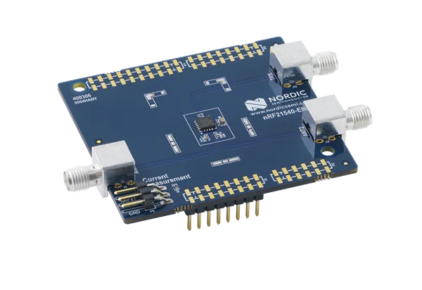
nRF21540 EK shield
Pin assignment
Shield connector pin |
SIGNAL |
FEM function |
|---|---|---|
D2 |
GPIO |
Mode Select |
D3 |
GPIO |
RX Enable |
D4 |
GPIO |
Antenna Select |
D5 |
GPIO |
TX Enable |
D9 |
GPIO |
Power Down |
D10 |
SPI CS |
Chip Select |
D11 |
SPI MOSI |
Serial Data In |
D12 |
SPI MISO |
Serial Data Out |
D13 |
SPI SCK |
Serial Clock |
Programming
Set -DSHIELD=nrf21540_ek when you invoke west build or cmake in your Zephyr application.
Alternatively, add the shield in the project’s CMakeLists.txt file:
set(SHIELD nrf21540_ek)
To build with SES, in the Extended Settings specify -DSHIELD=nrf21540_ek.
See Providing CMake options.
When building for a board with an additional network core, for example nRF5340, add an additional -DSHIELD variable with the childImageName_ parameter between -D and SHIELD to build for the network core as well.
For example:
west build -b nrf5340dk_nrf5340_cpuapp -- -DSHIELD=nrf21540_ek -Dmultiprotocol_rpmsg_SHIELD=nrf21540_ek
In this command, the childImageName_ parameter has the multiprotocol_rpmsg_ value and builds a multiprotocol application with support for 802.15.4 and Bluetooth.
The childImageName_ parameter can take the following values:
multiprotocol_rpmsg_for multiprotocol applications with support for 802.15.4 and Bluetooth802154_rpmsg_for applications with support for 802.15.4, but without support for Bluetoothhci_rpmsg_for application with support for Bluetooth, but without support for 802.15.4
References
Shields with 2-pin PA/LNA interface
The SKY66112-11EK is an example of a shield with the 2-pin PA/LNA interface.
Perform the following steps to use it:
Connect the shield to the development kit.
Follow the steps in the Adding support for Skyworks front-end module to add a FEM node in the devicetree.
Build your project.
Program the development kit with the created binary file.