Zigbee: Light switch
The Zigbee light switch sample can be used to change the state of light sources on other devices within the same Zigbee network.
You can use this sample together with the Zigbee network coordinator and the Zigbee light bulb to set up a basic Zigbee network.
This sample supports the optional Sleepy End Device behavior and Multiprotocol Bluetooth LE extension. It also supports Zigbee FOTA. See Activating sample extensions for details about how to enable these variants.
Overview
The light switch sample demonstrates the Zigbee End Device role and implements the Dimmer Light Switch profile.
Once the light switch is successfully commissioned, it sends a broadcast message to find devices with the implemented Level Control and On/Off clusters. The light switch remembers the device network address from the first response, at which point it can be controlled with the development kit buttons.
Sleepy End Device behavior
The light switch supports the Sleepy End Device behavior that enables the sleepy behavior for the end device, for a significant conservation of energy.
The sleepy behavior can be enabled by pressing Button 3 while the light switch sample is booting.
Multiprotocol Bluetooth LE extension
This optional extension demonstrates dynamic concurrent switching between two protocols, Bluetooth LE and Zigbee. It uses Nordic UART Service (NUS) library.
When this extension is enabled, you can use:
Buttons on the light switch device to operate on the Zigbee network
Nordic UART Service to operate on the Bluetooth LE network
Both networks are independent from each other.
To support both protocols at the same time, the Zigbee stack uses the IEEE 802.15.4 radio during the inactive time of the Bluetooth LE radio (using Multiprotocol Service Layer’s Timeslot API). Depending on the Bluetooth LE connection interval, the nRF52 development kits can spend up to 99% of the radio time on the Zigbee protocol.
Transmitting and receiving data when using this example does not break connection from any of the used radio protocols, either Bluetooth LE or Zigbee.
For more information about the multiprotocol feature, see Multiprotocol support for Thread and Zigbee.
Source file setup
This sample is split into the following source files:
The
mainfile to handle initialization and light switch basic behavior.An additional
nus_cmdfile for handling NUS commands.
Requirements
The sample supports the following development kits:
Hardware platforms |
PCA |
Board name |
Build target |
|---|---|---|---|
PCA10056 |
|
||
PCA10010 |
|
You can use one or more of the development kits listed above and mix different development kits.
For this sample to work, the following samples also need to be programmed:
The Zigbee network coordinator sample on one separate device.
The Zigbee: Light bulb sample on one or more separate devices.
Multiprotocol Bluetooth LE extension requirements
If you enable the Multiprotocol Bluetooth LE extension, make sure you have a phone or a tablet with the nRF Toolbox application installed.
Note
The Testing instructions refer to nRF Toolbox, but similar applications can be used as well, for example nRF Connect for Mobile.
User interface
- LED 3:
On and solid when the device is connected to a Zigbee network.
- LED 4:
On and solid when the light switch has found a light bulb to control.
- Button 1:
When the light bulb is turned off, turn it back on.
Pressing this button for a longer period of time increases the brightness of the light bulb.
- Button 2:
Turn off the light bulb connected to the network (light bulb’s LED 4). This option is available after the successful commissioning (light switch’s LED 3 turned on).
Pressing this button for a longer period of time decreases the brightness of the LED 4 of the connected light bulb.
Note
If the brightness level is at the minimum level, the effect of turning on the light bulb might not be noticeable.
Sleepy End Device behavior assignments
- Button 3:
When pressed while resetting the board, enable the Sleepy End Device behavior.
Multiprotocol Bluetooth LE extension assignments
- LED 1:
On and solid when a Bluetooth LE Central is connected to the NUS service. Available when using Nordic UART Service (NUS) in the multiprotocol configuration.
- UART command assignments:
The following command assignments are configured and used in nRF Toolbox when Testing multiprotocol Bluetooth LE extension:
n- Turn on the Zigbee light bulb.f- Turn off the Zigbee light bulb.t- Toggle the Zigbee light bulb on or off.i- Increase the brightness level of the Zigbee light bulb.d- Decrease the brightness level of the Zigbee light bulb.
If more than one light bulb is available in the network, these commands apply to all light bulbs in the network. See Testing multiprotocol Bluetooth LE extension for details.
Building and running
Make sure to enable the Zigbee stack before building and testing this sample. See Working with Zigbee for more information.
This sample can be found under samples/zigbee/light_switch in the nRF Connect SDK folder structure.
See Building and programming a sample application for information about how to build and program the application.
Activating sample extensions
To activate the optional extensions supported by this sample, modify OVERLAY_CONFIG in the following manner:
For the variant that supports Zigbee FOTA, set
overlay-fota.conf. Alternatively, you can configure Zigbee FOTA manually.Note
The
overlay-fota.conffile can be used only for nRF52840 DK.For the Multiprotocol Bluetooth LE extension, set
overlay-multiprotocol_ble.conf. Check Board names for the board name to use instead of thenrf52840dk_nrf52840.
See Providing CMake options for instructions on how to add this option. For more information about using configuration overlay files, see Important Build System Variables in the Zephyr documentation.
Testing
After programming the sample to your development kits, test it by performing the following steps:
Turn on the development kit that runs the network coordinator sample. When LED 3 turns on, this development kit has become the Coordinator of the Zigbee network.
Turn on the development kit that runs the light bulb sample. When LED 3 turns on, the light bulb has become a Router inside the network.
Tip
If LED 3 does not turn on, press Button 1 on the Coordinator to reopen the network.
Turn on the development kit that runs the light switch sample. When LED 3 turns on, the light switch has become an End Device, connected directly to the Coordinator.
Wait until LED 4 on the light switch node turns on. This LED indicates that the light switch found a light bulb to control.
You can now use buttons on the development kit to control the light bulb, as described in User interface.
Testing multiprotocol Bluetooth LE extension
To test the multiprotocol Bluetooth LE extension, complete the following steps after the standard Testing procedure:
Set up nRF Toolbox by completing the following steps:
Tap UART to open the UART application in nRF Toolbox.
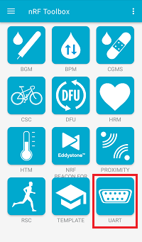
UART application in nRF Toolbox
Configure the UART commands by completing the following steps:
Tap the EDIT button in the top right corner of the application. The button configuration window appears.
Create the active application buttons by completing the following steps:
Bind the
ncommand to one of the buttons, with EOL set to LF and an icon of your choice.Bind the
fcommand to one of the buttons, with EOL set to LF and an icon of your choice.Bind the
tcommand to one of the buttons, with EOL set to LF and an icon of your choice.Bind the
dcommand to one of the buttons, with EOL set to LF and an icon of your choice.Bind the
icommand to one of the buttons, with EOL set to LF and an icon of your choice.
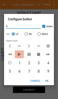
Configuring buttons in the UART application of nRF Toolbox
Tap the DONE button in the top right corner of the application.
Tap CONNECT and select the
Zigbee_Switchdevice from the list of devices.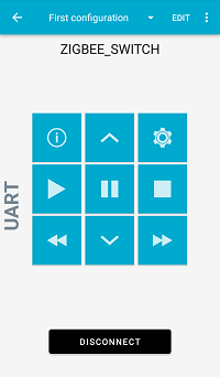
The UART application of nRF Toolbox after establishing the connection
Note
Observe that LED 1 on the light switch node is solid, which indicates that the Bluetooth LE connection is established.
In nRF Toolbox, tap the buttons you assigned:
Tap the
nandfcommand buttons to turn the LED on the Zigbee light bulb node on and off, respectively.Tap the
tcommand button two times to toggle the LED on the Zigbee light bulb node on and off.Tap the
ianddcommand buttons to make adjustments to the brightness level.
You can now control the devices either with the buttons on the development kits or with the NUS UART command buttons in the nRF Toolbox application.
Sample output
The sample logging output can be observed through a serial port. For more details, see How to connect with PuTTY.
Dependencies
This sample uses the following nRF Connect SDK libraries:
Zigbee subsystem:
zb_nrf_platform.hzigbee_helpers.hzb_error_handler.h
This sample uses the following nrfxlib libraries:
In addition, it uses the following Zephyr libraries:
The following dependencies are added by the multiprotocol Bluetooth LE extension:
Zephyr’s Bluetooth:
include/bluetooth/bluetooth.hinclude/bluetooth/gatt.hinclude/bluetooth/hci.hinclude/bluetooth/uuid.hinclude/bluetooth/services/nus.h