 |
nRF51 SDK - S130 SoftDevice
|
 |
nRF51 SDK - S130 SoftDevice
|
SPI RAW protocol implements Serialization PHY API for SPI interface.
In standard implementation SPI RAW interface uses 6 lines: four standard (CLK,MOSI,MISO,/CS) and two additional (/RDY, /REQ).
Application processor is a SPI bus master, nRF51 chip is a slave device.
A 5 wire variant, which does not use /RDY line ( SPI_5W RAW protocol) was also implemented .
SPI RAW protocol facilitates transfer of packets with variable length.
Due to variable length of the packets and master-slave architecture of SPI interface, each packet transfer is done in a simplex mode.
Every bus transaction transfers data either from application processor to nRF51 or from nRF51 to application processor, but not simultaneously in both directions.
Transfer of data consists of bus transactions. Each transaction starts with falling edge and ends with rising edge of /CS signal.
Read transactions are not interleaved with write transactions. Once started, all transactions needed to read or write of the whole packet must be completed.
Both /REQ, /RDY lines are active low and driven by slave device.
Line /REQ, when asserted, signals that slave device has data to be read.
Line /RDY when asserted, signals that slave device is ready for a transaction.
Payload transfer is preceded by 2 bytes of physical layer header, which defines the size of packet.
Header is transmitted as least significant byte first.
SPI slave device uses DMA, and due to the maximum size of DMA buffers, packets are divided into frames.
The size of frame is determined by the MTU constant, which is currently set to 255 (SER_PHY_SPI_MTU_SIZE = 255).
All packets bigger than MTU are divided into frames with maximum size of MTU.
For example, a packet with the length of 1024 bytes, will be divided into 5 frames (1024= 4x255 + 4)
[255][255][255][255][4]
Each frame is transferred as one bus transaction.
MTU size may be set to lower value to accommodate different architecture of the master device.
Packets are transmitted in a following format :
TX_RAW_PACKET = [TX_HEADER][TX_FRAME][TX_FRAME][TX_FRAME]...

Packet length is send as a [TX_HEADER]=[0x0004] in the first transaction.
When transaction ends, signal /RDY is deasserted by slave device.
After some 100us, when DMA buffers are serviced and set for next transaction, /RDY line is asserted again.
Second transaction transfers payload [TX_FRAME]=[0x00, 0x78, 0x00, 0x03].
Packets are received in a following format :
SPI_RAW_PACKET = [ZERO_HEADER][RX_HEADER][RX_FRAME][RX_FRAME][RX_FRAME]...

Slave request for reading of a packet is signalled by assertion of /REQ line.
When master device is ready to read a packet, it sends [ZERO_HEADER]=[0x0000].
[ZERO_HEADER] is an indication, that master device is initiating a packet read operation.
When [ZERO_HEADER] is detected by slave, /REQ line is deasserted.
In the next transaction a [RX_HEADER]=[0x0006] defining received payload length is read by master device.
Third transaction transfers payload of 6 bytes [RX_FRAME]=[0x01, 0x7C, 0x00, 0x00, 0x00, 0x00].
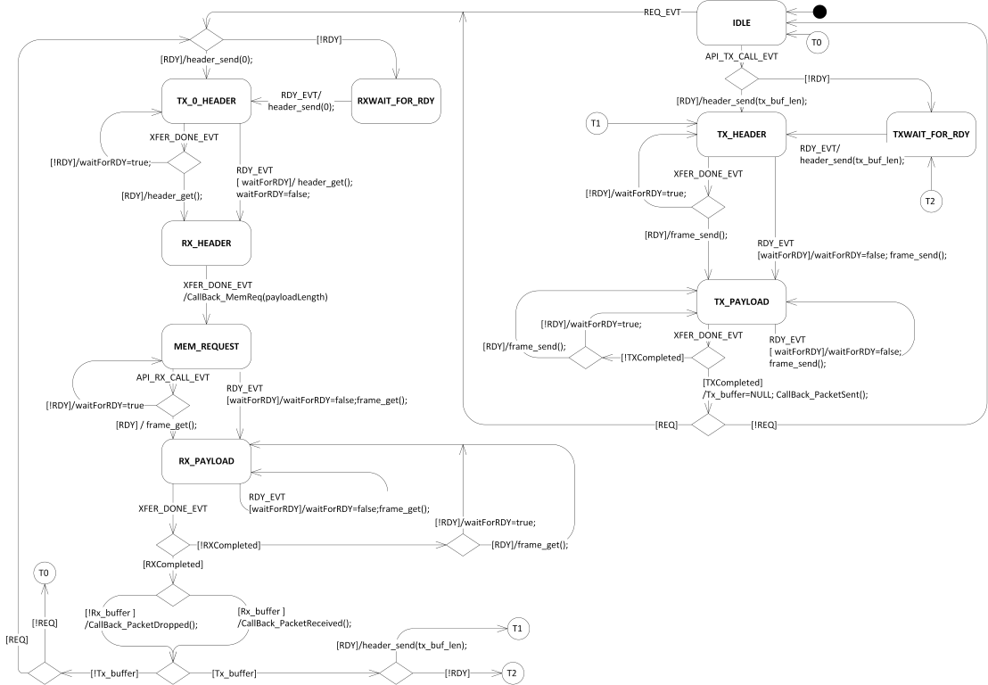
SPI RAW protocol for master device is implemented in ser_phy_spi_phy_driver_master file.
The operation of ser_phy_switch_state() function is illustrated by UML state diagram .

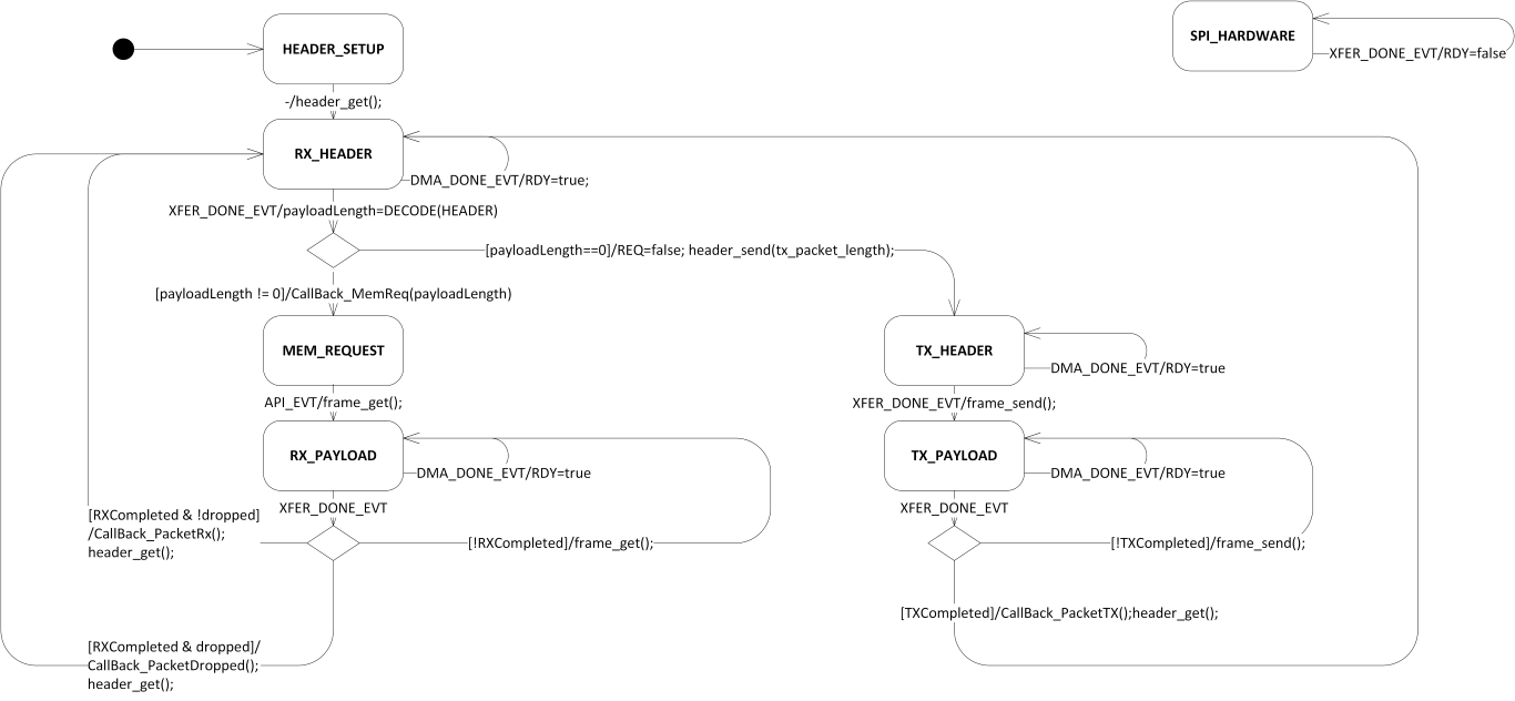
SPI RAW protocol for slave device is implemented in ser_phy_spi_phy_driver_slave file.
The operation of spi_slave_event_handle() function is illustrated by UML state diagram.
