 |
nRF51 SDK
|
|
nRF51 SDK
|
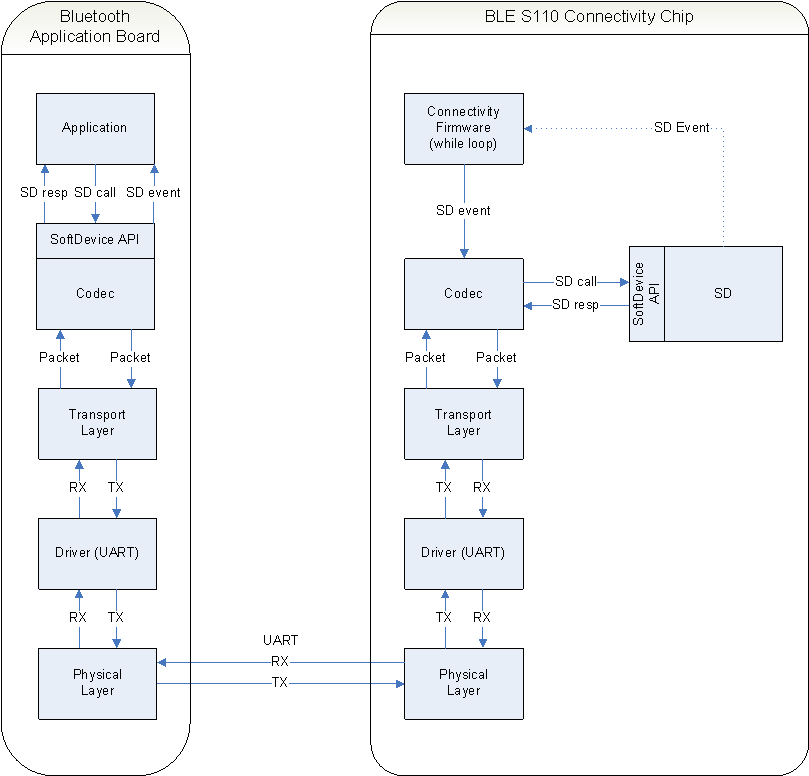
The BLE S110 Serialization makes it possible to place a Bluetooth Application on an application chip and connect it to a connectivity chip running the BLE nrf518_lib_ble_s110.
Connectivity Chip: The nRF51822 chip running the BLE S110 SoftDevice.
Bluetooth Application Board: The nRF51822 chip running a serialized application, where the BLE S110 SoftDevice is replaced by the Commands Encoder and Events Decoder. The nRF51822 does not have the BLE S110 SoftDevice.
On the Bluetooth Application Board, the BLE S110 SoftDevice is replaced by a codec implementing the S110 SoftDevice API. All function calls to the codec will be serialized and transmitted to the BLE S110 Connectivity Chip using the Transport Layer and UART driver. This design makes it possible to substitute an existing layer, such as UART with SPI, without affecting the codec.
The BLE S110 Connectivity Chip will decode the serialized commands from the Bluetooth Application Board and execute the corresponding function in the S110 SoftDevice.
Any event from the S110 SoftDevice is encoded by the codec and transmitted to the Bluetooth Application Board using the the transport layer and UART.
On the Bluetooth Application Board the event is decoded and passed to the application.
BLE S110 Serialization simplifies the serialization of an existing Bluetooth application, since limited modifications are needed in the application itself. Serialization of an existing application requires Command Encoder, Event Decoder, HCI Transport and SLIP module which are used in the project instead of the S110 SoftDevice.
See Serialization nRFgo Motherboard Setup - Serialization on how to flash and wire a Bluetooth Application Board with a BLE S110 Connectivity chip.
The BLE S110 Serialization example transmits and receives commands, command responses, and events over UART.
In Bluetooth two UART transport layer protocols are commonly in use.
The Transport Layer for spec. 1.1, H4, is a very simple and lightweight transport layer, which works very well in noise-free environment and reliable UART.
The Transport Layer for specification 4.0 is more complex and overhead on the wire due to transmission of acknowledgement packets and re-transmissions. The use of acknowledgement packets make the transport layer more robust and reliable but it has associated costs in terms of larger code size, larger memory footprint. It also makes transmission duration longer because of retransmission.
A brief comparison between HCI Transport Layer for specification 1.1 and 4.0 can be seen in the table below.
| HCI UART Transport Layer, v 1.1 (H4) | HCI Transport Layer, v4.0 |
| Simple | Complex |
| Fast (No ACK packets) | Slower (ACK packets) |
| Unreliable in noisy environments | Very reliable (retransmission) |
| Smaller code/memory footprint | Larger code/memory footprint |
The BLE S110 Serialization examples provides the ability to use the reliable Three-wire Transport Layer, ver. 4.0.
The Three-wire Transport Layer offers reliable transport layer when developing a two chip solution where the nRF51822 is used as the connectivity chip. For the prototyping setup presented in nRFgo Motherboard Setup - Serialization , this solution ensures correct transmission and retransmission of packets even when long cables, high baud rates, and noisy environments are taken into consideration. This allows the developer to concentrate on developing the right application without concerns for the communication layer.
It guarantees reliable transfer of packets when connecting the nRF51822 chip to PC UART / USB-UART connectors, which can vary in reliability, especially at higher baud rates.
It is recommended during prototyping and/or early development of nRF51822 product, HCI Transport Layer V4.0 could be used. However after gaining confidence and ensuring robustness and reliability at application level for the final product, it is recommended to switch over to the HCI UART Transport Layer, H4.
The nRF51822 chip offers a reliable UART, even at high baud rates. Therefore acknowledgement of packets and retransmission can be disabled in order to reduce the memory/flash footprint and reduce power consumption. This can be achieved by removing the acknowledgement packets and retransmission from hci_transport.c .
The image below shows the internal architecture of a serialized BLE S110 SoftDevice.
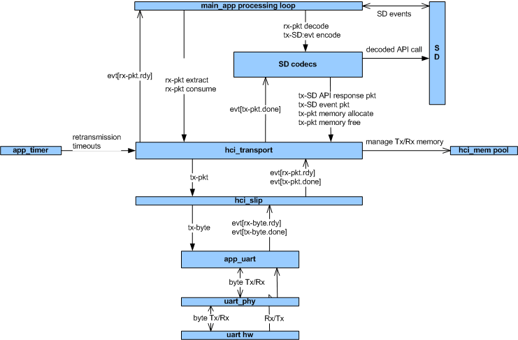
The image below shows the various threads of execution within the serialized BLE S110 Connectivity Chip.
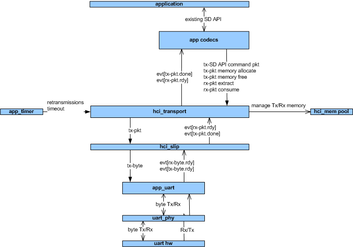
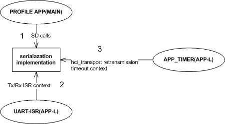
The image below shows an example internal architecture of an application chip controlling the serialized BLE S110 SoftDevice.
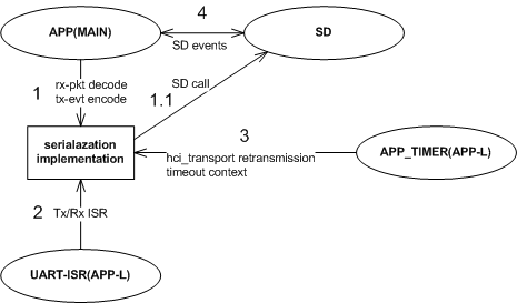
The image below shows an example of various threads of execution which could be executing within an application chip controlling the serialized BLE S110 SoftDevice.
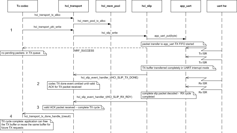
The image below shows an MSC of a single basic TX path cycle.
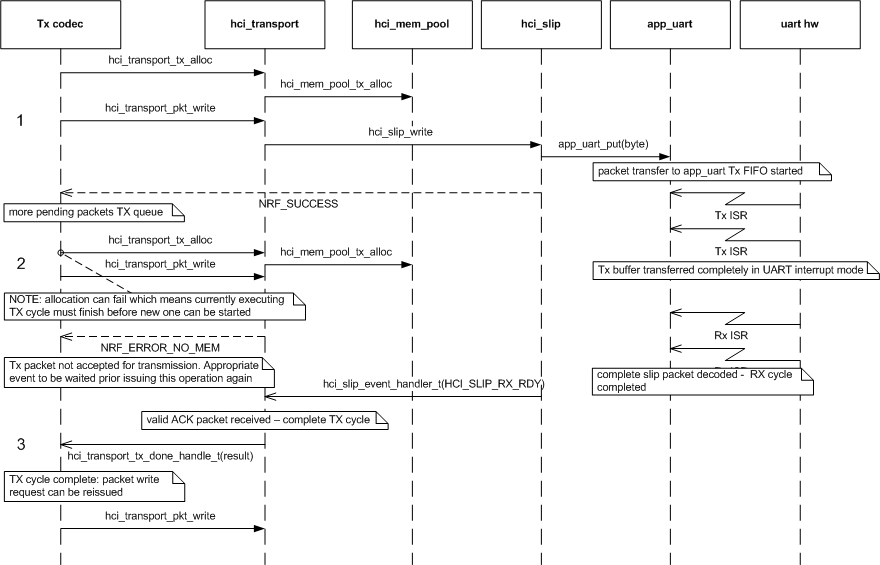
The image below shows an MSC of a TX path cycle where TX path is 1st stopped due TX queue been filled up and after correct event reception resumed.
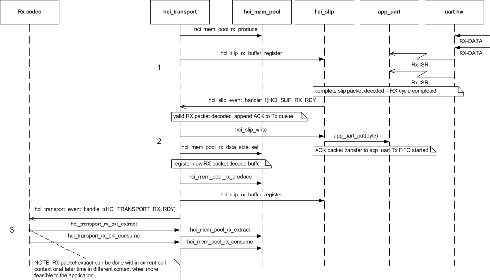
The image below shows an MSC of a single basic RX path cycle.
 1.8.3.1
