 |
nRF51 SDK - S120 SoftDevice
|
|
nRF51 SDK - S120 SoftDevice
|
The QDEC Example demonstrates the use of the quadrature decoder (QDEC) peripheral.
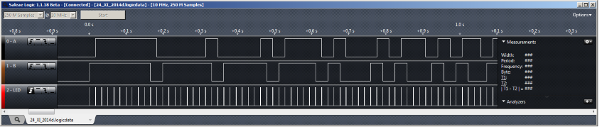
The example uses the software quadrature encoder simulator QENC to produce input. The quadrature encoder simulator uses one channel of the GPIOTE module. The state of the encoder changes according to the sampling clock generated by the LED output.
The QDEC inputs A and B must be connected to the QENC outputs A and B, respectively. The QDEC LED output must be connected to the QENC LED input.
QENC produces a variable number of positive and negative pulses in an infinite loop. These pulses are synchronized with the bursts of clock impulses that are generated by QDEC at the LED output. The pulses are counted by QDEC operating in a REPORT mode, and the count is compared with the pulses that are generated by QENC.
The name of the example is qdec_pca10028. If you are not using the Keil Pack Installer, you can find the source code and project file of the example in the following folder: <InstallFolder>\Nordic\nrf51\examples\peripheral\qdec
Configuration:
The example works in auto-test mode. If there is a difference between the number of pulses counted and generated, the application stops.
 1.8.3.1
