 |
nRF51 SDK - S310 SoftDevice
|
|
nRF51 SDK - S310 SoftDevice
|
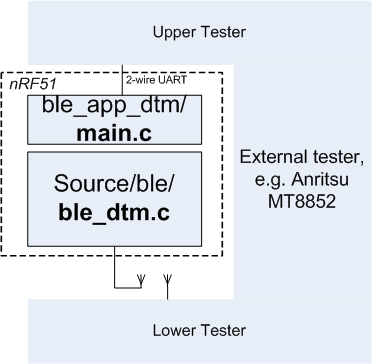
The DTM application enables the DTM test functions described in Bluetooth Specification Version 4.0, Vol. 6, Part F.
The purpose of DTM is to test the operation of the radio at the physical level, such as
Test procedures are defined the document "<i>Bluetooth</i> Low Energy RF PHY Test Specification", Document no RF-PHY.TS/4.0.0. Conformance tests are carried out by dedicated test equipment (such as the Anritsu MT8852 or similar), the nRF51 with the DTM application as the DUT.
The nRF51 DTM application includes two parts:
The DTM application contains a driver for a 2-wire UART interface, mapping two-octet commands and events as specified by the BLE DTM specification to the dtmlib.
Source code and project file for the DTM application can be found in the <InstallFolder>\Nordic\nrf51\Board\nrf6310\direct_test_mode folder.
Source code and project file for the ble_dtm.c module can be found in the <InstallFolder>\Nordic\nrf51\Source\ble folder. The header file ble_dtm.h is found in the <InstallFolder>\Nordic\nrf51\Include\ble folder.
The implementation is self contained, and requires no BLE protocol stack for its operation. The MPU is initialized in the standard way (files startup_nRF51502.s and system_nRF51502.c. The dtmlib fuction dtm_init() will do all configuration of interrupts, timers and radio. Initialization of the UART is done by the dtm_serial2w code.
main.c may be replaced with other interface implementations, such as an HCI interface, USB or other interface required by the Upper Tester.
The interface to the Lower Tester uses the antenna connector of the nRF51. While in principle an aerial may be used, conformance tests cover reading the transmission power delivered by the DUT; hence a coax connection between the DUT and the Lower Tester is employed for all conformance testing.
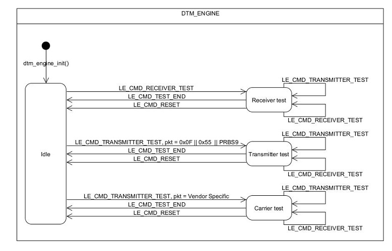
ble_dtm.c, function dtm_cmd(), implements the four commands defined by the BLE standard
In the dtm_cmd() interface, each of the parameters (cmd, freq, length, payload) is a word size value. Note that parameter values currently supported is limited to those defined for BLE. (HCI allows a greater value range for use with BR/EDR.)
DTM events,
are polled using the dtm_event_get() function.
The BLE 2-wire UART DTM interface standard reserves Packet Type (payload parameter) binary value '11' for a Vendor Specific Packet Payload. The dtm_serial2w adaptation layer maps this to value 0xFFF..FFF in the dtm_cmd() interface. The rationale for this mapping is to allow later extensions to a 4-bit Packet Type field, as specified in the HCI interface and in the DTM PDU layout.
The Vendor Specific payload (parameter 4) is interpreted as follows:
If Command, parameter 1, is set to Transmitter Test (binary '10') and parameter 4, payload, to Vendor Specific (binary '11' in the 2wire physical interface, all bits set to 1 in the dtmlib interface):
length) is set to 0 (symbol CARRIER_TEST), an unmodulated carrier is turned on atthe channel indicated by parameter 2 (freq). It remains turned on until a TEST_END or RESET command is issued.length) equal to 1 (symbol CARRIER_TEST_STUDIO), is used by the nRFgo studio to indicate an unmodulated carrier is turned on at the channel. It remains turned on until a TEST_END or RESET command is issued.length) is set to 2 (symbol SET_TX_POWER), parameter 2 (length) sets the tx power in dBm, ranging from -40 to +4 in steps of 4, 0 dBm being the reset value. The tx power can only be modified while no Transmitter Test or Receiver Test is running.freq) is set to 3 (symbol SELECT_TIMER), parameter 2 (length) selects the timer to be used by dtmlib for Transmitter Test timing. Valid timer identifiers are 0, 1 and 2. Configuring the timer to be used allows dtmlib to be integrated in a larger test environment where other modules may be occupying the default timer (timer 0).freq) and 4 (length) are reserved.main.c is a sample adaptation layer, implementing the UART interface as specified in Volume 6, part F, chapter 3 of the Bluetooth specification.
The default selection of GPIO pins are pin 16 for RX and pin 17 for TX which corresponds to the pin usage in the nRFgo Motherboard Setup (nRF6310) and are defined in boards/nrf6310.h and can be changed by editing the values of the symbols RX_PIN_NUMBER and TX_PIN_NUMBER.
Conformance testing is done using a certified tester. The setup depends on the actual tester, and details about the test operation must be found from the tester documentation.
The BLE DTM UART interface standard specifies
The default bit rate of the DTM UART driver is 19200 bps, which is supported by most certified testers.
 1.8.3.1
