 |
nRF51 SDK - S310 SoftDevice
|
|
nRF51 SDK - S310 SoftDevice
|
The Blinky Example shows how to configure the GPIO pins as outputs which can also be used to drive LEDs on the hardware delivered in the nRF51822 Development Kit.
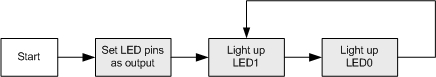
When the application starts, two GPIO pins are configured as outputs to drive the LEDs. The applications then loops while alternating between turning on LED0 and LED1 every 500ms.
The source code and project file are available for both development and evaluation boards and is located in the following folders:
<InstallFolder>\Nordic\nrf51822\Board\nrf6310\blinky_example
<InstallFolder>\Nordic\nrf51822\Board\pca10001\blinky_example
<InstallFolder>\Nordic\nrf51422\Board\pca10003\blinky_example
Instructions on how to set up the nRFgo Motherboard: nRFgo Motherboard Setup (nRF6310).
LED assignments:
The Blinky Example Application can be tested as follows:
 1.8.3.1
