 |
nRF51 SDK - S210 SoftDevice
|
 |
nRF51 SDK - S210 SoftDevice
|
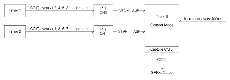
The PPI Example uses PPI module to communicate between three timers. One timer (T2) is used to generate events every odd second, that is at 1,3,5,7 ... seconds. These events are used for creating another timer (T0) start a task through PPI which is running in counter mode. The other timer (T1) is used to generate events every even second, that is at 2,4,6,8 ... seconds and are used to trigger stop task for timer T0 through another channel of PPI. The main program loop is running to trigger the counter every 100 ms. The timer T0 counter values are passed to GPIO port. This port can be used to turn on the LEDs to confirm that the LEDs change binary value every 100 ms for a second then PAUSE for one second. The pause is because timer T2 creates an event that passes through PPI generating a T0 stop task. Even though the main loop triggers the timer T0 counter to increment, no changes are noticed as timer T0 is stopped. After one second timer T1 generates an event which is passed though PPI to create a timer T0 start task, and then the LEDS light up again. It uses the hardware delivered in the nRF51822 Development Kit.

The application starts with configuring the three timers. Timer 0 is configured to blink the LEDs, timer 1 is configured to generate events on even numbered seconds, and timer 2 is configured to generate events on odd numbered seconds. The PPI is configured to make timer 0 stop and start at Timer 1 compare match and timer 2 compare match, respectively. The main loop increments timer 0 and updates the LEDs every 100ms.
Instructions on how to set up the nRFgo Motherboard: nRFgo Motherboard Setup (nRF6310).
LED assignments:
The PPI Example Application can be tested as follows: