ITE IT82XX2 series
Overview
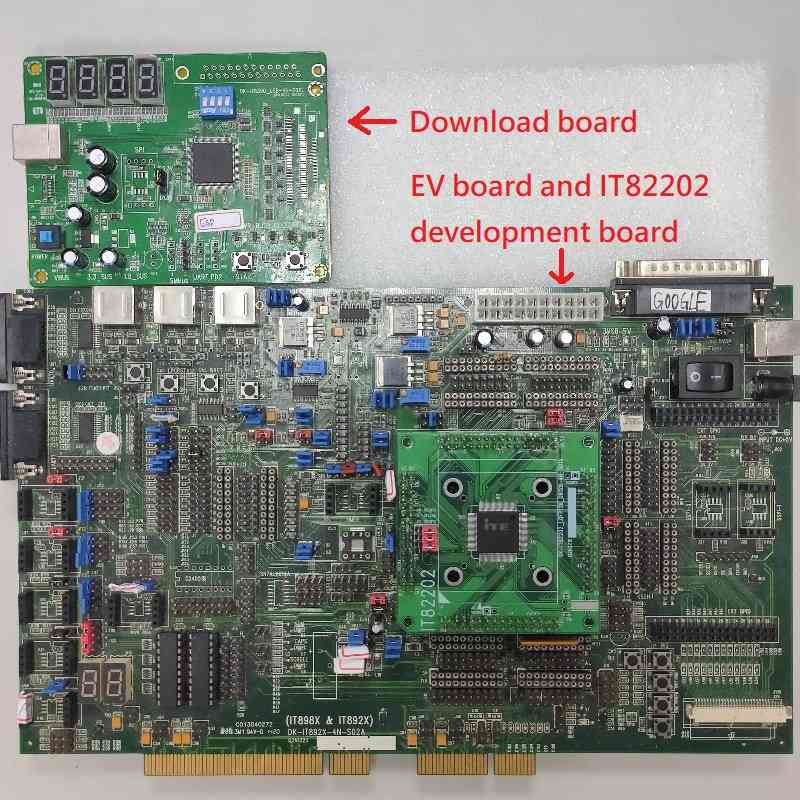
The IT82XX2 is a 32-bit RISC-V microcontroller. And a highly integrated embedded controller with system functions. It is suitable for mobile system applications. The picture below is the IT82202 development board (also known as it82xx2_evb) and its debug card.
To find out more about ITE, visit our World Wide Web at:ITE’s website [1]
Hardware
The IT82XX2 series contains different chip types(ex, it82202, it82302), and they support different hardware features. Listing the IT82202 hardware features as following:
RISC-V RV32IMAFC instruction set
4KB instruction cache size
256KB SRAM in total
Built-in 32.768 kHz clock generator
Embedded Flash, 512K/1024K-byte e-flash
eSPI, SSPI, SPI slave, BRAM, KBC, PECI, UART
GPIO, PWM, ADC, INTC, WUC, Timer, Watchdog, KB scan, JTAG
Support 6 Voltage Comparator
Support Cryptographic Engine
6 SMBus channels, with 6 DMA controller, compatible with I2C
USB 2.0 Full-speed Controller
USB Type-c CC Logic
USB Power Delivery
Supported Features
currently supports the following hardware features:
Interface |
Controller |
Driver/Component |
|---|---|---|
NVIC |
on-chip |
interrupt controller |
FLASH |
on-chip |
flash controller |
PINCTRL |
on-chip |
pin controller |
ESPI |
on-chip |
espi |
PECI |
on-chip |
peci |
UART |
on-chip |
serial |
GPIO |
on-chip |
gpio |
PWM |
on-chip |
pwm |
ADC |
on-chip |
adc |
TIMER |
on-chip |
timer |
WATCHDOG |
on-chip |
watchdog |
KSCAN |
on-chip |
kscan |
SENSOR |
on-chip |
voltage comparator |
I2C |
on-chip |
i2c |
Other hardware features are not currently supported by Zephyr.
The default configuration can be found in the boards/riscv/it82xx2_evb/it82xx2_evb_defconfig Kconfig file.
Programming and debugging on it82202
In order to upload the application to the device, you’ll need our flash tool and Download board. You can get them at: ITE’s website [1].
Wiring
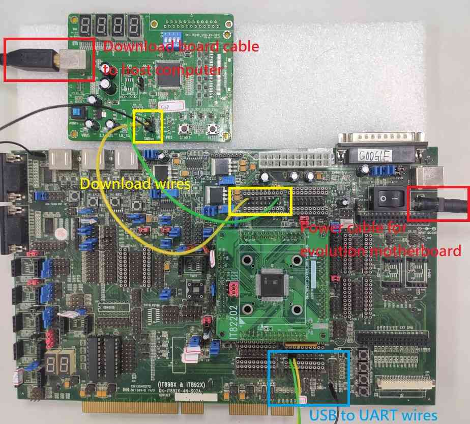
Connect the Download Board to your host computer using the USB cable.
Connect the it82xx2_evb to the evolution motherboard.
Connect the Download Board J5 to J41 on the evolution motherboard.
Connect the USB to UART wire to J33 on the evolution motherboard.
Note
Be careful during connection! Use separate wires to connect I2C pins with pins on the it82xx2_evb board. Wiring connection is described in the table below.
J5 Connector
it82xx2_evb J41 Connector
2
E0
3
E7
4
GND
For USB to UART cable, connect the evolution motherboard as below:
USB to UART cable
Evolution motherboard J33 Connector
RX
B0
TX
B1
GND
GND
Building
Build Hello World application as you would normally do (see :Zephyr Getting Started Guide [2]):.
# From the root of the zephyr repository
west build -b it82xx2_evb samples/hello_world
The file
zephyr.binwill be created by west.
Flashing
Windows
Use the winflash tool to program a zephyr application to the it82xx2 board flash.
Open the winflash tool and make sure the order you open the switch is right. First, turn on the Download board switch. Second, turn on the it82xx2_evb board switch. Then, configure your winflash tool like below.
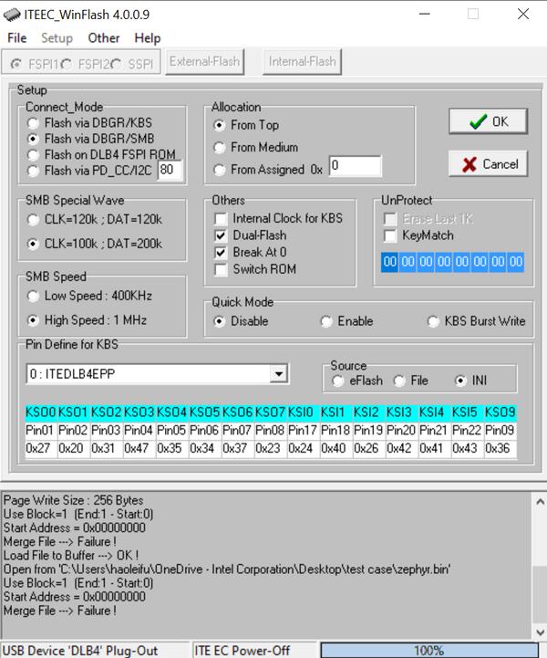
Using the winflash tool flash
zephyr.bininto your ITE board. First, click theLoadbutton and select yourzephyr.binfile. Second, clickrunto flash the image into board.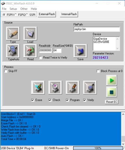
At this point, you have flashed your image into ITE board and it will work if you turn on the ITE board. You can use a terminal program to verify flashing worked correctly.
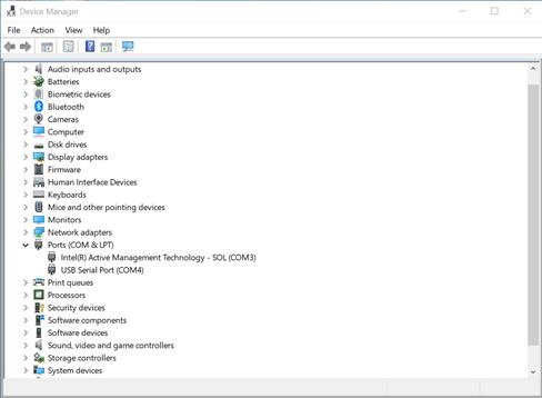
For example, open device manager to find the USB Serial Port(COM4) and use your terminal program to connect it(Speed: 115200).
Turn on the it82xx2_evb board switch, you should see
"Hello World! it82xx2_evb"sent by the board. If you don’t see this message, press the Reset button and the message should appear.
Ubuntu
Run your favorite terminal program to listen for output. Under Linux the terminal should be
/dev/ttyUSB0. Do not close it.For example:
$ minicom -D /dev/ttyUSB0 -b 115200
Open a second terminal window and use the Linux flash tool to flash your board.
$ sudo ~/itetool/ite -f build/zephyr/zephyr.bin
Note
The source code of ITE tool can be downloaded here: https://www.ite.com.tw/uploads/product_download/itedlb4-linux-v106.tar.bz2
Split first and second terminal windows to view both of them. You should see
"Hello World! it82xx2_evb"in the first terminal window. If you don’t see this message, press the Reset button and the message should appear.
Debugging
it82xx2_evb board can be debugged by connecting USB to UART. We can write commands and read messages through minicom in the Ubuntu terminal.
Troubleshooting
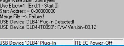
If the flash tool reports a failure, re-plug the 8390 Download board or power cycle the it82xx2_evb board and try again.