ICE-V Wireless
Overview
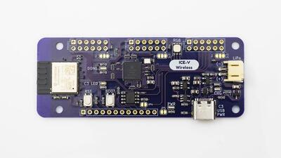
The ICE-V Wireless is a combined ESP32C3 and iCE40 FPGA board.
See the ICE-V Wireless Github Project for details.
ICE-V Wireless
Hardware
This board combines an Espressif ESP32-C3-MINI-1 (which includes 4MB of flash in the module) with a Lattice iCE40UP5k-SG48 FPGA to allow WiFi and Bluetooth control of the FPGA. ESP32 and FPGA I/O is mostly uncommitted except for the pins used for SPI communication between ESP32 and FPGA. Several of the ESP32C3 GPIO pins are available for additonal interfaces such as serial, ADC, I2C, etc.
For details on ESP32-C3 hardware please refer to the following resources:
For details on iCE40 hardware please refer to the following resources:
Supported Features
The ICE-V Wireless board configuration supports the following hardware features:
Interface |
Controller |
Driver/Component |
|---|---|---|
PMP |
on-chip |
arch/riscv |
INTMTRX |
on-chip |
intc_esp32c3 |
PINMUX |
on-chip |
pinctrl_esp32 |
USB UART |
on-chip |
serial_esp32_usb |
GPIO |
on-chip |
gpio_esp32 |
UART |
on-chip |
uart_esp32 |
I2C |
on-chip |
i2c_esp32 |
SPI |
on-chip |
spi_esp32_spim |
ADC |
on-chip |
Other hardware features have not been enabled yet for this board.
Connections and IOs
The ICE-V Wireless provides 1 row of reference, ESP32-C3, and iCE40 signals brought out to J3, as well as 3 PMOD connectors for interfacing directly to the iCE40 FPGA. Note that several of the iCE40 pins brought out to the PMOD connectors are capable of operating as differential pairs.
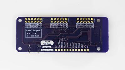
ICE-V Wireless (Back)
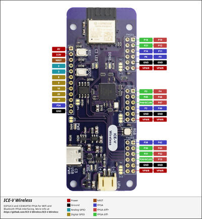
The J3 pins are 4V, 3.3V, NRST, GPIO2, GPIO3, GPIO8, GPIO9, GPIO10, GPIO20, GPIO21, FPGA_P34, and GND. Note that GPIO2 and GPIO3 may be configured for ADC operation.
For PMOD details, please refer to the PMOD Specification and the image below.
Programming and Debugging
Programming and debugging for the ICE-V Wireless ESP32-C3 target is incredibly easy 🎉 following the steps below.
Building and Flashing
ESP-IDF bootloader
The board is using the ESP-IDF bootloader as the default 2nd stage bootloader. It is build as a subproject at each application build. No further attention is expected from the user.
MCUboot bootloader
User may choose to use MCUboot bootloader instead. In that case the bootloader must be build (and flash) at least once.
There are two options to be used when building an application:
Sysbuild
Manual build
Note
User can select the MCUboot bootloader by adding the following line
to the board default configuration file.
`
CONFIG_BOOTLOADER_MCUBOOT=y
`
Sysbuild
The sysbuild makes possible to build and flash all necessary images needed to bootstrap the board with the ESP32 SoC.
To build the sample application using sysbuild use the command:
west build -b icev_wireless --sysbuild samples/hello_world
By default, the ESP32 sysbuild creates bootloader (MCUboot) and application images. But it can be configured to create other kind of images.
Build directory structure created by sysbuild is different from traditional Zephyr build. Output is structured by the domain subdirectories:
build/
├── hello_world
│   └── zephyr
│       ├── zephyr.elf
│       └── zephyr.bin
├── mcuboot
│    └── zephyr
│       ├── zephyr.elf
│       └── zephyr.bin
└── domains.yaml
Note
With --sysbuild option the bootloader will be re-build and re-flash
every time the pristine build is used.
For more information about the system build please read the Sysbuild (System build) documentation.
Manual build
During the development cycle, it is intended to build & flash as quickly possible. For that reason, images can be build one at a time using traditional build.
The instructions following are relevant for both manual build and sysbuild. The only difference is the structure of the build directory.
Note
Remember that bootloader (MCUboot) needs to be flash at least once.
For the Hello, world! application, follow the instructions below.
# From the root of the zephyr repository
west build -b icev_wireless samples/hello_world
west flash
Open the serial monitor using the following command:
$ west espressif monitor
After the board has automatically reset and booted, you should see the following message in the monitor:
***** Booting Zephyr OS vx.x.x-xxx-gxxxxxxxxxxxx *****
Hello World! icev_wireless
Debugging
As with much custom hardware, the ESP32C3 modules require patches to OpenOCD that are not upstreamed. Espressif maintains their own fork of the project. The custom OpenOCD can be obtained by running the following extension:
west espressif install
Note
By default, the OpenOCD will be downloaded and installed under $HOME/.espressif/tools/zephyr directory (%USERPROFILE%/.espressif/tools/zephyr on Windows).
The Zephyr SDK uses a bundled version of OpenOCD by default. You can overwrite that behavior by adding the
-DOPENOCD=<path/to/bin/openocd> -DOPENOCD_DEFAULT_PATH=<path/to/openocd/share/openocd/scripts>
parameter when building.
Here is an example for building the Hello World application.
# From the root of the zephyr repository
west build -b icev_wireless samples/hello_world -- -DOPENOCD=<path/to/bin/openocd> -DOPENOCD_DEFAULT_PATH=<path/to/openocd/share/openocd/scripts>
west flash
You can debug an application in the usual way. Here is an example for the Hello World application.
# From the root of the zephyr repository
west build -b icev_wireless samples/hello_world
west debug