nRF5340 Audio overview and firmware architecture
Each nRF5340 Audio application corresponds to one specific LE Audio role: unicast client (gateway), unicast server (headset), broadcast source (gateway), or broadcast sink (headset). The gateway receives the audio data from external sources (USB or line input/I2S) and forwards it to one or more headsets. The headset is a receiver device that plays back the audio it gets from the gateway, and will act as earbuds, headphones, a speaker, hearing aids, or similar.
Each nRF5340 Audio application is configured for one specific LE Audio mode: the connected isochronous stream (CIS, unicast) mode or in the broadcast isochronous stream (BIS) mode. See Application modes for more information.
The applications use the same code base, but use different main.c files and include different modules and libraries depending on the configuration.
You might need to configure and program two applications for testing the interoperability, depending on your use case. See the testing steps for each of the application for more information.
Application modes
Each application works either in the connected isochronous stream (CIS) mode or in the broadcast isochronous stream (BIS) mode.
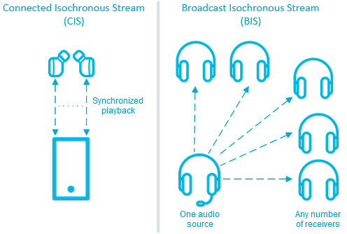
CIS and BIS mode overview
- Connected Isochronous Stream (CIS)
CIS is a bidirectional communication protocol that allows for sending separate connected audio streams from a source device to one or more receivers. The gateway can send the audio data using both the left and the right ISO channels at the same time, allowing for stereophonic sound reproduction with synchronized playback.
This is the mode available for the unicast applications (unicast client and unicast server). In this mode, you can use the nRF5340 Audio development kit in the role of the gateway, the left headset, or the right headset.
In the current version of the nRF5340 Audio unicast client, the application offers both unidirectional and bidirectional communication. In the bidirectional communication, the headset device will send audio from the on-board PDM microphone. See Selecting the CIS bidirectional communication in the application description for more information.
You can also enable a walkie-talkie demonstration. In this demonstration, the gateway device will send audio from the on-board PDM microphone instead of using USB or the line-in. See Enabling the walkie-talkie demo in the application description for more information.
- Broadcast Isochronous Stream (BIS)
BIS is a unidirectional communication protocol that allows for broadcasting one or more audio streams from a source device to an unlimited number of receivers that are not connected to the source.
This is the mode available for the broadcast applications (broadcast source for headset and broadcast sink for gateway). In this mode, you can use the nRF5340 Audio development kit in the role of the gateway or as one of the headsets. Use multiple nRF5340 Audio development kits to test BIS having multiple receiving headsets.
Note
In the BIS mode, you can use any number of nRF5340 Audio development kits as receivers.
The audio quality for both modes does not change, although the processing time for stereo can be longer.
Firmware architecture
The following figure illustrates the software layout for the nRF5340 Audio application:

nRF5340 Audio high-level design (overview)
The network core of the nRF5340 SoC runs the SoftDevice Controller, which is responsible for receiving the audio stream data from hardware layers and forwarding the data to the Bluetooth LE host on the application core. The controller implements the lower layers of the Bluetooth Low Energy software stack. See SoftDevice Controller for more information about the controller, and SoftDevice Controller for LE Isochronous Channels for information on how it implements ISO channels used by the nRF5340 Audio applications.
The application core runs both the Bluetooth LE Host from Zephyr and the application layer. The application layer is composed of a series of modules from different sources. These modules include the following major ones:
Peripheral modules from the nRF Connect SDK:
I2S
USB
SPI
TWI/I2C
UART (debug)
Timer
LC3 encoder/decoder
Application-specific Bluetooth modules for handling the Bluetooth connection:
Management - This module handles scanning and advertising, in addition to general initialization, controller configuration, and transfer of DFU images.
Stream - This module handles the setup and transfer of audio in the Bluetooth LE Audio context. It includes submodules for CIS (unicast) and BIS (broadcast).
Renderer - This module handles rendering, such as volume up and down.
Content Control - This module handles content control, such as play and pause.
Application-specific custom modules, including the synchronization module (part of I2S-based firmware for gateway and headsets) - See Synchronization module overview for more information.
Since the application architecture is the same for all applications and the code before compilation is shared to a significant degree, the set of modules in use depends on the chosen audio inputs and outputs (USB or analog jack).
Note
In the current versions of the applications, the bootloader is disabled by default. Device Firmware Update (DFU) can only be enabled when Building and programming using script. See Configuring FOTA upgrades for details.
Communication between modules
Communication between modules is primarily done through Zephyr’s Zephyr bus (zbus) to make sure that there are as few dependencies as possible. Each of the buses used by the applications has their message structures described in nrf5340_audio_common.h.
USB-based firmware for gateway
The following figures show an overview of the modules currently included in the firmware of applications that use USB.
In this firmware design, no synchronization module is used after decoding the incoming frames or before encoding the outgoing ones. The Bluetooth LE RX FIFO is mainly used to make decoding run in a separate thread.
Broadcast source USB-based firmware

nRF5340 Audio modules for the broadcast source using USB
Unicast client USB-based firmware

nRF5340 Audio modules for the unicast client using USB
I2S-based firmware for gateway and headsets
The following figure shows an overview of the modules currently included in the firmware of applications that use I2S.
The Bluetooth LE RX FIFO is mainly used to make audio_datapath.c (synchronization module) run in a separate thread.
Broadcast source I2S-based firmware

nRF5340 Audio modules for the broadcast source using I2S
Broadcast sink I2S-based firmware

nRF5340 Audio modules for the broadcast sink using I2S
Unicast client I2S-based firmware

nRF5340 Audio modules for the unicast client using I2S
Unicast server I2S-based firmware

nRF5340 Audio modules for the unicast server using I2S
Synchronization module overview
The synchronization module (audio_datapath.c) handles audio synchronization.
To synchronize the audio, it executes the following types of adjustments:
Presentation compensation
Drift compensation
The presentation compensation makes all the headsets play audio at the same time, even if the packets containing the audio frames are not received at the same time on the different headsets. In practice, it moves the audio data blocks in the FIFO forward or backward a few blocks, adding blocks of silence when needed.
The drift compensation adjusts the frequency of the audio clock to adjust the speed at which the audio is played. This is required in the CIS mode, where the gateway and headsets must keep the audio playback synchronized to provide True Wireless Stereo (TWS) audio playback. As such, it provides both larger adjustments at the start and then continuous small adjustments to the audio synchronization. This compensation method counters any drift caused by the differences in the frequencies of the quartz crystal oscillators used in the development kits. Development kits use quartz crystal oscillators to generate a stable clock frequency. However, the frequency of these crystals always slightly differs. The drift compensation makes the inter-IC sound (I2S) interface on the headsets run as fast as the Bluetooth packets reception. This prevents I2S overruns or underruns, both in the CIS mode and the BIS mode.
See the following figure for an overview of the synchronization module.

nRF5340 Audio synchronization module overview
Both synchronization methods use the SDU reference timestamps (sdu_ref) as the reference variable.
If the device is a gateway that is using I2S as audio source and the stream is unidirectional (gateway to headsets), sdu_ref is continuously being extracted from the LE Audio Controller Subsystem for nRF53 on the gateway.
The extraction happens inside the unicast_client.c and broadcast_source.c files’ send function.
The sdu_ref values are then sent to the gateway’s synchronization module, and used to do drift compensation.
Note
Inside the synchronization module (audio_datapath.c), all time-related variables end with _us (for microseconds).
This means that sdu_ref becomes sdu_ref_us inside the module.
As the nRF5340 is a dual-core SoC, and both cores need the same concept of time, each core runs a free-running timer in an infinite loop.
These two timers are reset at the same time, and they run from the same clock source.
This means that they should always show the same values for the same points in time.
The network core of the nRF5340 running the LE controller for nRF53 uses its timer to generate the sdu_ref timestamp for every audio packet received.
The application core running the nRF5340 Audio application uses its timer to generate cur_time and frame_start_ts.
After the decoding takes place, the audio data is divided into smaller blocks and added to a FIFO. These blocks are then continuously being fed to I2S, block by block.
See the following figure for the details of the compensation methods of the synchronization module.

nRF5340 Audio’s state machine for compensation mechanisms
The following external factors can affect the presentation compensation:
The drift compensation must be synchronized to the locked state (
DRIFT_STATE_LOCKED) before the presentation compensation can start. This drift compensation adjusts the frequency of the audio clock, indicating that the audio is being played at the right speed. When the drift compensation is not in the locked state, the presentation compensation does not leave the init state (PRES_STATE_INIT). Also, if the drift compensation loses synchronization, moving out ofDRIFT_STATE_LOCKED, the presentation compensation moves back toPRES_STATE_INIT.When audio is being played, it is expected that a new audio frame is received in each ISO connection interval. If this does not occur, the headset might have lost its connection with the gateway. When the connection is restored, the application receives a
sdu_refnot consecutive with the previously receivedsdu_ref. Then the presentation compensation is put intoPRES_STATE_WAITto ensure that the audio is still in sync.
Note
When both the drift and presentation compensation are in state locked (DRIFT_STATE_LOCKED and PRES_STATE_LOCKED), LED2 lights up.
Synchronization module flow
The received audio data in the I2S-based firmware devices follows the following path:
The SoftDevice Controller running on the network core receives the compressed audio data.
The controller, running in the Bluetooth: HCI IPC sample on the nRF5340 SoC network core, sends the audio data to the Zephyr Bluetooth LE host running on the nRF5340 SoC application core.
The host sends the data to the stream control module.
The data is sent to a FIFO buffer.
The data is sent from the FIFO buffer to the
audio_datapath.csynchronization module. Theaudio_datapath.cmodule performs the audio synchronization based on the SDU reference timestamps. Each package sent from the gateway gets a unique SDU reference timestamp. These timestamps are generated on the headset Bluetooth LE controller (in the network core). This enables the creation of True Wireless Stereo (TWS) earbuds where the audio is synchronized in the CIS mode. It does also keep the speed of the inter-IC sound (I2S) interface synchronized with the sending and receiving speed of Bluetooth packets.The
audio_datapath.cmodule sends the compressed audio data to the LC3 audio decoder for decoding.The audio decoder decodes the data and sends the uncompressed audio data (PCM) back to the
audio_datapath.cmodule.The
audio_datapath.cmodule continuously feeds the uncompressed audio data to the hardware codec.The hardware codec receives the uncompressed audio data over the inter-IC sound (I2S) interface and performs the digital-to-analog (DAC) conversion to an analog audio signal.