Overview
This example demonstrates how the lwIP stack can be used on Nordic's 6lowpan interface to send data on a remote UDP port. Remote port number 9000 is assumed in this example. Local port number 9001 is used to send requests and receive responses. Request and response formats used for this example are described in the sections UDP Request Format and UDP Response Format, respectively.
- Note
- The UDP remote server address used to send the requests is assumed to be 2004::02AA:BBFF:FECC:DD:EEFF. The example must be modified to match the address of the server in use. The lwIP UDP server example used for the demo has the BD address of 00:DA:BB:C9:A4:E9 and the prefix assigned to the server by the router is 2003::/64, and then the client must use the server's global address of 2003::02DA:BBFF:FEC9:A4E9. See Creating link-local IPv6 addresses for details.
UDP Request Format
In order to demonstrate data exchange on the UDP port, the application is designed to expect an 8-byte echo request in the following format from the UDP Client.
| Field | Sequence number in uint32 format | 'P' | 'i' | 'n' | 'g' |
| Size (octets) | 4 (Network Order) | 1 | 1 | 1 | 1 |
UDP Response Format
In response to a request from the client, this application responds back to a request with a 8-byte response packet with the following format:
| Field | Requested Sequence number in uint32 format | 'P' | 'o' | 'n' | 'g' |
| Size (octets) | 4 (Network Order) | 1 | 1 | 1 | 1 |
The UDP server could be a PC application communicating to the UDP client on the kit, as shown in Figure 1 below.

Figure 1: Setup of the lwIP based IPv6 UDP client application.
Or, the UDP server could be the example server application included in the SDK responding to requests from this example application in Figure 2.

Figure 2: Setup of the lwIP based IPv6 UDP client with UDP server application.
Common Modules Dependency and Usage
This section summarizes the usage of nRF51 resources and common modules in the examples apart from the IoT 6lowpan and lwIP stack library.
| Module | Inclusion/Usage | Description |
| Timer | 1 | One timer is used to periodically service the lwIP with 200 ms interval. |
| Button | 0 | No buttons are used in the example. |
| LEDs | 2 | LEDs are used to indicate the application states. See the LED assignment section. |
| Adv Data Encoder | Yes | The device name used is 'LwIPUDPClient', IPSP Service UUID is included in the UUID list. |
| Scheduler | No | Scheduler is not used for processing stack events. |
| UART Trace | Included not enabled | Tracing is included but not enabled by default. |
- Note
- The lwIP library used for this example is under BSD-style license; this is different from the Nordic SDK license. The license text can be found at <InstallFolder>/Nordic/nrf51/external/lwip/license.txt.
Setup
The name of the example is iot_lwip_udp_client. The source code and project file of the example can be found at: <InstallFolder>/Nordic/nrf51/examples/iot/udp/lwip/client
See below for a short state diagram that describes the application states.
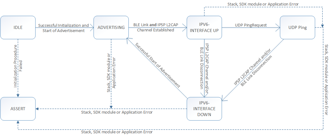
Figure 3: Application State Diagram.
LED assignments
| Application State | LED 1 State | LED 2 State |
| Idle | OFF | OFF |
| Advertising | ON | OFF |
| IPv6 Interface Up | OFF | ON |
| IPv6 Interface Down | ON | OFF |
| UDP Ping | Refer to table below | Refer to table below |
| ASSERT | ON | ON |
By using the LEDs on the board, the remainder after division of the received Sequence number by 4 is displayed in the following manner.
| Value | Binary | LED 1 State | LED 2 State |
| 0 | 00000000 | OFF | OFF |
| 1 | 00000001 | ON | OFF |
| 2 | 00000010 | OFF | ON |
| 3 | 00000011 | ON | ON |
- Note
- If the application asserts, it is halted.
-
This application is not power optimized!
Testing
See Connecting devices to the router for a list of relevant Linux commands.
- Compile and program the application. Observe that the advertising LED is lit.
- Prepare the Linux router device by initializing the 6LoWPAN module.
- Discover the advertising device by using the hcitool lescan command.
- Connect to the discovered device from the Linux console by using the Bluetooth 6LoWPAN connect command.
- Now the advertising LED is turned off and the connected LED is lit.
- Run the Wireshark or hcidump program and observe the btX interface.
- An ICMP ping can be used on the link-local and on the global IPv6 address assigned to the device to ensure the device is reachable.
- Note
- To find the global address, use the prefix assigned to the interface in Router Advertisement.
- Use a UDP server to listen on UDP port number 9000, and observe if the client packets are received in the format described in section UDP Request Format. When sending response packets as described in UDP Response Format, observe the LED light pattern as described in LED assignments.
- Note
- This example is designed to complement the lwIP UDP server example, and they will work together provided this application is modified to use the address of the server application.
- Disconnect from the device by using the Bluetooth 6LoWPAN disconnect command.
- Observe that only the advertising LED is lit.
Python UDP Server Example
Below is a Python server example that listens on port 9000 and sends back responses for requests received on the port. Request and response structure are according to the format specified in sections UDP Request Format and UDP Response Format, respectively.
import socket
import struct
#This example assumes that the global IPv6 address 2004::C0AA:BBFF:FECC:DDEE is available on one of the network interfaces.
SERVER_PORT = 9000
SERVER_ADDR = '2004::C0AA:BBFF:FECC:DDEE'
sock = socket.socket(socket.AF_INET6, socket.SOCK_DGRAM)
server_addr = (SERVER_ADDR, SERVER_PORT, 0, 0)
sock.bind(server_addr)
while 1 :
recv_data = sock.recvfrom(8)
print recv_data
rx_sequence_number = 0
rx_sequence_number = struct.unpack("!I", recv_data[0][:4])[0]
print ("Rx Sequence Number %08x" % rx_sequence_number)
data = struct.pack("!i", (rx_sequence_number))
data += 'Pong'
sock.sendto(data, recv_data[1])
sock.close()
del sock
Troubleshooting guide
- It is possible that the global address is not immediately available on the connection as the Neighbor Discovery, Router Advertisement, and Duplicate Address Detection procedures take a few seconds to complete.
- In case no global address is assigned to the nRF51, the lwIP stack does not permit sending packets to a global address. This means that if a UDP request packet was received from a global address, the response will not be sent as there is no global address available to this application. This is usually detected with the ERR_RTE error code when calling the udp_sendto_ip6 API of lwIP stack in the application.
- If you observe that the server responses are received at the btX interface but the client never receives them, it is possible that the forwarding between networks is not enabled. This can be done on Linux by using the command
sysctl -w net.ipv6.conf.all.forwarding=1
- In case this example is reachable and sending requests every 200 ms, but these requests do not make it to the listening server, it is possible that the application is not configured with the correct remote server address. Verify that the address m_remote_addr in the application matches the server address.

 1.8.3.1
