Bluetooth: Mesh light switch
The Bluetooth mesh light switch sample can be used to change the state of light sources on other devices within the same mesh network. It also demonstrates how to use Bluetooth® mesh models by using the Generic OnOff Client model in an application.
Use the light switch sample with the Bluetooth: Mesh light sample to demonstrate its function in a Bluetooth mesh network.
This sample also provides the Low Power node support.
Requirements
The sample supports the following development kits:
Hardware platforms |
PCA |
Board name |
Build target |
|---|---|---|---|
PCA20053 |
|
||
PCA10095 |
|
||
PCA10040 |
|
||
PCA10056 |
|
||
PCA10100 |
|
||
PCA10112 |
|
You need at least two development kits:
One development kit where you program this sample application (the client)
One (or more) development kit(s) where you program the Bluetooth: Mesh light sample application (the server(s)), and configure according to the mesh light sample’s testing guide
For provisioning and configuring of the mesh model instances, the sample requires a smartphone with Nordic Semiconductor’s nRF Mesh mobile app installed in one of the following versions:
Note
If you build this application for Thingy:53, it enables additional features. See Thingy:53 application guide for details.
When built for an _ns build target, the sample is configured to compile and run as a non-secure application with Cortex-M Security Extensions enabled.
Therefore, it automatically includes Trusted Firmware-M that prepares the required peripherals and secure services to be available for the application.
Low Power node requirements
The configuration overlay overlay-lpn.conf is optimized for the following boards:
nrf52dk_nrf52832
nrf52840dk_nrf52840
nrf52833dk_nrf52833
However, the same configuration can be applied to other platforms that support the Bluetooth mesh Light Switch sample, as long as the device supports at least four buttons.
Overview
The Bluetooth mesh light switch sample demonstrates how to set up a mesh client model application, and control LEDs with the Bluetooth mesh using the Generic OnOff models. To display any functionality, the sample must be paired with a device with the Bluetooth: Mesh light sample running in the same mesh network.
In both samples, devices are nodes with a provisionee role in a mesh network. Provisioning is performed using the nRF Mesh mobile app. This mobile application is also used to configure key bindings, and publication and subscription settings of the Bluetooth mesh model instances in the sample to enable them to communicate with the servers.
The Generic OnOff Client model is used for manipulating the Generic OnOff state associated with the Generic OnOff Server model. The light switch sample implements the Generic OnOff Client model.
The sample instantiates up to four instances of the Generic OnOff Client model to control the state of LEDs on servers (implemented by the Bluetooth: Mesh light sample). One instance of the Generic OnOff Client model is instantiated in the light switch sample for each button available on the development kit that is used. When a user presses any of the buttons, an OnOff Set message is sent out to the configured destination address.
After provisioning and configuring the mesh models supported by the sample using the nRF Mesh mobile app, you can control the LEDs on the other (server) development kit(s) from the app.
Provisioning
Provisioning is handled by the Bluetooth mesh provisioning handler for Nordic DKs. It supports four types of out-of-band (OOB) authentication methods, and uses the Hardware Information driver to generate a deterministic UUID to uniquely represent the device.
Models
The following table shows the mesh light switch composition data for this sample:
Element 1 |
Element 2 |
Element 3 |
Element 4 |
|---|---|---|---|
Config Server |
Gen. OnOff Client |
Gen. OnOff Client |
Gen. OnOff Client |
Health Server |
|||
Gen. OnOff Client |
Note
When used with Thingy:53, Elements 3 and 4 are not available. Thingy:53 supports only two buttons.
The models are used for the following purposes:
Generic OnOff Client instances in available elements are controlled by the buttons on the development kit.
Config Server allows configurator devices to configure the node remotely.
Health Server provides
attentioncallbacks that are used during provisioning to call your attention to the device. These callbacks trigger blinking of the LEDs.
The model handling is implemented in src/model_handler.c, which uses the DK Buttons and LEDs library to detect button presses on the development kit.
If the model is configured to publish to a unicast address, the model handler calls bt_mesh_onoff_cli_set() to turn the LEDs of a mesh light device on or off.
The response from the target device updates the corresponding LED on the mesh light switch device.
If the model is configured to publish to a group address, it calls bt_mesh_onoff_cli_set_unack() instead, to avoid getting responses from multiple devices at once.
Low Power node support
The mesh light switch sample can also be run as a Low Power node (LPN), giving the possibility of lowering the power consumption.
While running the sample with the LPN configuration, the fourth Generic OnOff Client instance will be omitted. Instead, button 4 will be used to temporarily enable Node ID advertisement on the LPN device.
Running continuous proxy advertisement with Network ID consumes considerable power, and is therefore disabled in the configuration. Instead, the user can manually enable the Node ID advertisement for a period of 30 seconds by pressing Button 4 on the device. This will give the user a short period of time to connect directly to the LPN, and thus perform necessary configuration of the device.
After the connection to the LPN is terminated, and the Node ID advertisement has stopped, the LPN will return to its previous state.
Friendship establishment will happen automatically after provisioning the LPN light switch, given that a Bluetooth: Mesh light sample is running and is provisioned into the same mesh network.
Note
While running the sample as an LPN, logging over the serial interface will be disabled.
Power consumption measurements
The following table shows a list of the supported boards for the LPN configuration, the average power consumption running as a standard (non-LPN) node, and the average power consumption running as an LPN node:
Board |
Avg. consumption non-LPN |
Avg. consumption LPN |
|---|---|---|
nrf52dk_nrf52832 |
7.14 mA |
13.69 µA |
nrf52840dk_nrf52840 |
6.71 mA |
14.63 µA |
nrf52833dk_nrf52833 |
6.10 mA |
14.43 µA |
The following applies to the LPN measurements presented in this table:
They are taken after the provisioning and configuration have completed, and after the LPN has established a friendship to a neighboring node.
The measurement period is approximately ten minutes, and without any light switch events (for example when idle).
The current consumption is measured using the Power Profiler Kit II (PPK2).
The measurements are done on the SoC only (meaning the measurements do not include power consumed by development kit LEDs for example).
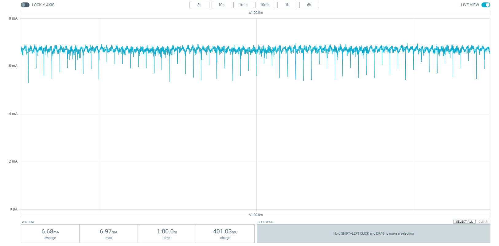
Power consumption for nRF52840 running as standard node (Captured in nRF Connect for Desktop: Power Profiler).
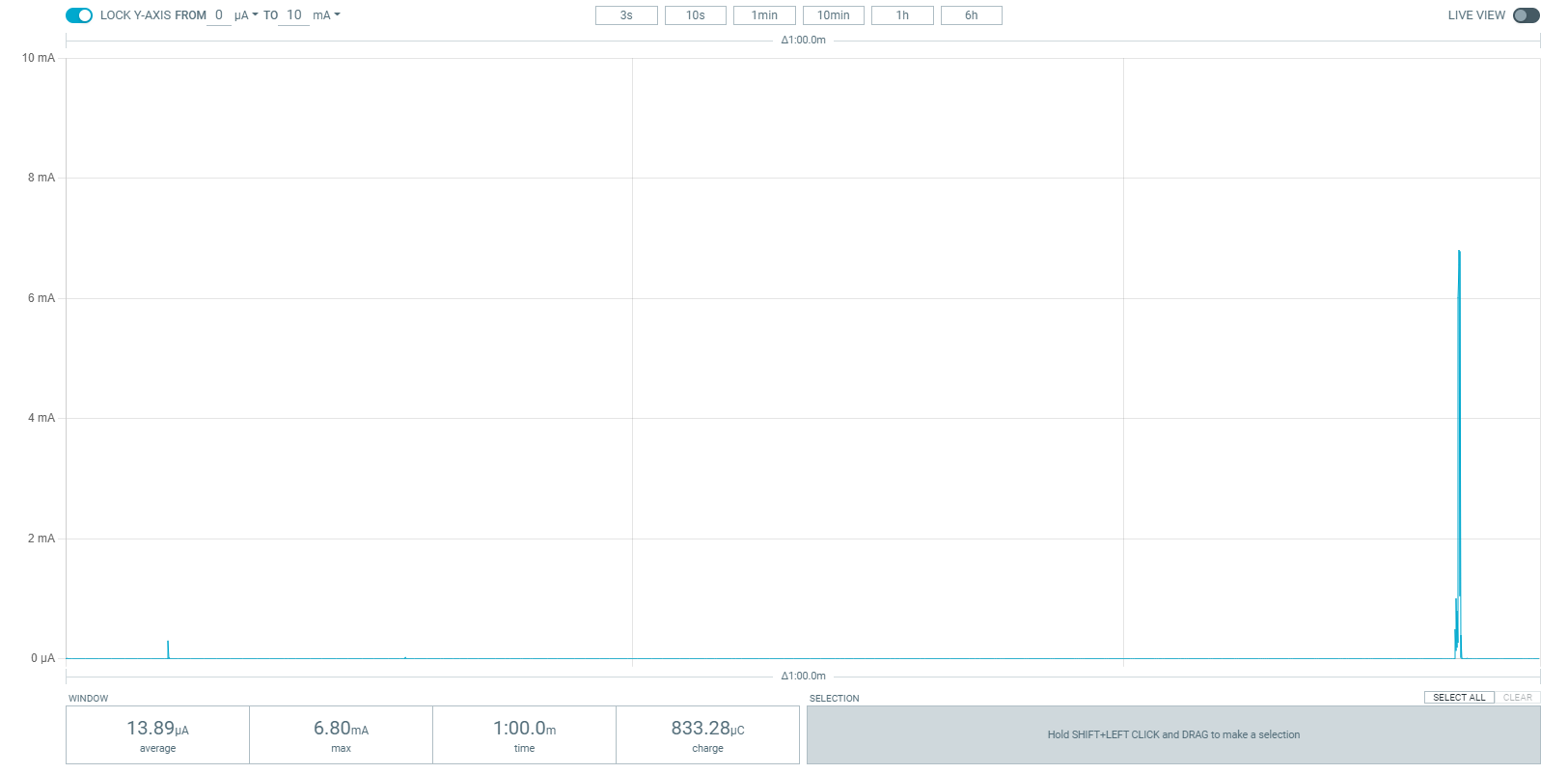
Power consumption for nRF52840 running as LPN, showing consumed power over a single LPN polling period. The rightmost spike represents the LPN polling the friend node. (Captured in nRF Connect for Desktop: Power Profiler).
User interface
- Buttons:
During the provisioning process, the buttons can be used for OOB input. Once the provisioning and configuration are completed, the buttons are used to initiate certain actions and control the respective Generic OnOff Client instances. When pressed, the button publishes an OnOff message using the configured publication parameters of its model instance, and toggles the LED state on a mesh light device.
- LEDs:
During the provisioning process, on board LEDs are used to output the OOB actions. Once the provisioning and configuration are completed, the LEDs are used to reflect the status of actions, and they show the last known OnOff state of the corresponding button.
Note
Thingy:53 supports only one RGB LED. Each RGB LED channel is used as separate LED.
The LPN assignments
- Button 4:
When pressed, enables the Node ID advertisement for a short period of time.
Configuration
See Configuring your application for information about how to permanently or temporarily change the configuration.
For nRF5340 and Thingy:53, the extended advertiser has to be set manually for the network core, because the Bluetooth® Low Energy does not know that the Bluetooth mesh is enabled when built for this core. This is already done for this sample by setting CONFIG_BT_EXT_ADV=y for the network core.
Source file setup
The light switch sample is split into the following source files:
LPN configuration
To make the light switch run as an LPN, set OVERLAY_CONFIG to overlay-lpn.conf when building the sample.
For example, when building from the command line, use the following command:
west build -b <BOARD> -p -- -DOVERLAY_CONFIG="overlay-lpn.conf"
The configuration overlay overlay-lpn.conf enables the LPN feature, and alters certain configuration options to further lower the power consumption.
To review the specific alterations, open and inspect the overlay-lpn.conf file.
For more information about using configuration overlay files, see Important Build System Variables in the Zephyr documentation.
FEM support
You can add support for the nRF21540 front-end module to this sample by using one of the following options, depending on your hardware:
Build the sample for one board that contains the nRF21540 FEM, such as nrf21540dk_nrf52840.
Manually create a devicetree overlay file that describes how FEM is connected to the nRF5 SoC in your device. See Set devicetree overlays for different ways of adding the overlay file.
Provide nRF21540 FEM capabilities by using a shield, for example the nRF21540 EK shield that is available in the nRF Connect SDK. In this case, build the project for a board connected to the shield you are using with an appropriate variable included in the build command. This variable instructs the build system to append the appropriate devicetree overlay file. For example, to build the sample from the command line for an nRF52833 DK with the nRF21540 EK attached, use the following command within the sample directory:
west build -b nrf52833dk_nrf52833 -- -DSHIELD=nrf21540_ekThis command builds the application firmware. See Programming nRF21540 EK for information about how to program when you are using a board with a network core, for example nRF5340 DK.
Each of these options adds the description of the nRF21540 FEM to the devicetree. See Working with RF front-end modules for more information about FEM in the nRF Connect SDK.
To add support for other front-end modules, add the respective devicetree file entries to the board devicetree file or the devicetree overlay file.
Building and running
Make sure to enable the Bluetooth mesh in nRF Connect SDK before building and testing this sample. See Bluetooth mesh user guide for more information.
This sample can be found under samples/bluetooth/mesh/light_switch in the nRF Connect SDK folder structure.
When built as firmware image for the _ns build target, the sample has Cortex-M Security Extensions (CMSE) enabled and separates the firmware between Non-Secure Processing Environment (NSPE) and Secure Processing Environment (SPE).
Because of this, it automatically includes the Trusted Firmware-M (TF-M).
To read more about CMSE, see Processing environments.
To build the sample with Visual Studio Code, follow the steps listed on the How to build an application page in the nRF Connect for VS Code extension documentation. See Building and programming an application for other building and programming scenarios and Testing and debugging an application for general information about testing and debugging in the nRF Connect SDK.
Testing
Note
The light switch sample cannot demonstrate any functionality on its own, and needs a device with the Bluetooth: Mesh light sample running in the same mesh network. Before testing mesh light switch, go through the mesh light’s testing guide with a different development kit.
After programming the sample to your development kit, you can test it by using a smartphone with nRF Mesh mobile app installed. Testing consists of provisioning the device and configuring it for communication with the mesh models.
Provisioning the device
The provisioning assigns an address range to the device, and adds it to the mesh network. Complete the following steps in the nRF Mesh app:
Tap Add node to start scanning for unprovisioned mesh devices.
Select the Mesh Light Switch device to connect to it.
Tap Identify, and then Provision, to provision the device.
When prompted, select an OOB method and follow the instructions in the app.
Once the provisioning is complete, the app returns to the Network screen.
Configuring models
See Configuring mesh models using the nRF Mesh mobile app for details on how to configure the mesh models with the nRF Mesh mobile app.
Note
When configuring mesh models using the nRF Mesh mobile app, make sure that you are connected directly to the Mesh Light Switch LPN when configuring the LPN. When using the mobile app for iOS, make sure that automatic proxy connection is disabled.
Configure the Generic OnOff Client model on each element on the Mesh Light Switch node:
Bind the model to Application Key 1.
Set the publication parameters:
Destination/publish address: Set the Publish Address to the first unicast address of the Mesh Light node.
Retransmit count: Set the count to zero (Disabled), to prevent the model from sending each button press multiple times.
Once the provisioning and the configuration of the client node and at least one of the server nodes are complete, you can use buttons on the client development kit. The buttons will control the LED lights on the associated servers, as described in User interface.
Dependencies
This sample uses the following nRF Connect SDK libraries:
In addition, it uses the following Zephyr libraries:
include/drivers/hwinfo.h-
include/kernel.h
-
include/bluetooth/bluetooth.h
-
include/bluetooth/mesh.h
The sample also uses the following secure firmware component: