ICE-V Wireless
Overview
The ICE-V Wireless is a combined ESP32C3 and iCE40 FPGA board.
See the ICE-V Wireless Github Project for details.
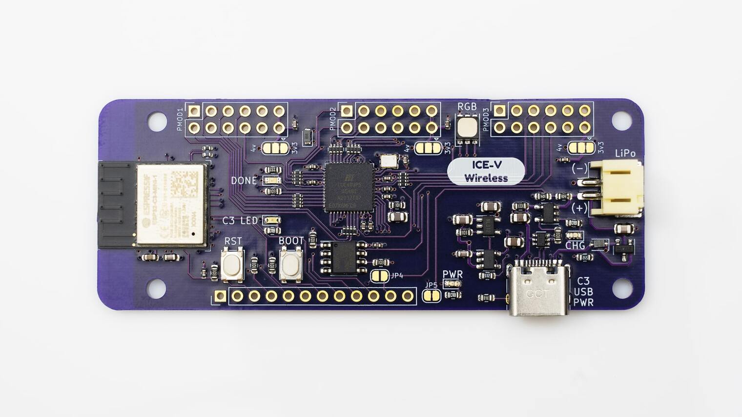
Fig. 209 ICE-V Wireless
Hardware
This board combines an Espressif ESP32-C3-MINI-1 (which includes 4MB of flash in the module) with a Lattice iCE40UP5k-SG48 FPGA to allow WiFi and Bluetooth control of the FPGA. ESP32 and FPGA I/O is mostly uncommitted except for the pins used for SPI communication between ESP32 and FPGA. Several of the ESP32C3 GPIO pins are available for additonal interfaces such as serial, ADC, I2C, etc.
For details on ESP32-C3 hardware please refer to the following resources: * ESP32-C3-MINI-1 Datasheet * ESP32-C3 Datasheet * ESP32-C3 Technical Reference Manual
For details on iCE40 hardware please refer to the following resources: * iCE40 UltraPlus Family Datasheet
Supported Features
The ICE-V Wireless board configuration supports the following hardware features:
Interface |
Controller |
Driver/Component |
|---|---|---|
PMP |
on-chip |
arch/riscv |
INTMTRX |
on-chip |
intc_esp32c3 |
PINMUX |
on-chip |
pinctrl_esp32 |
USB UART |
on-chip |
serial_esp32_usb |
GPIO |
on-chip |
gpio_esp32 |
UART |
on-chip |
uart_esp32 |
I2C |
on-chip |
i2c_esp32 |
SPI |
on-chip |
spi_esp32_spim |
ADC |
on-chip |
Other hardware features have not been enabled yet for this board.
Connections and IOs
The ICE-V Wireless provides 1 row of reference, ESP32-C3, and iCE40 signals brought out to J3, as well as 3 PMOD connectors for interfacing directly to the iCE40 FPGA. Note that several of the iCE40 pins brought out to the PMOD connectors are capable of operating as differential pairs.
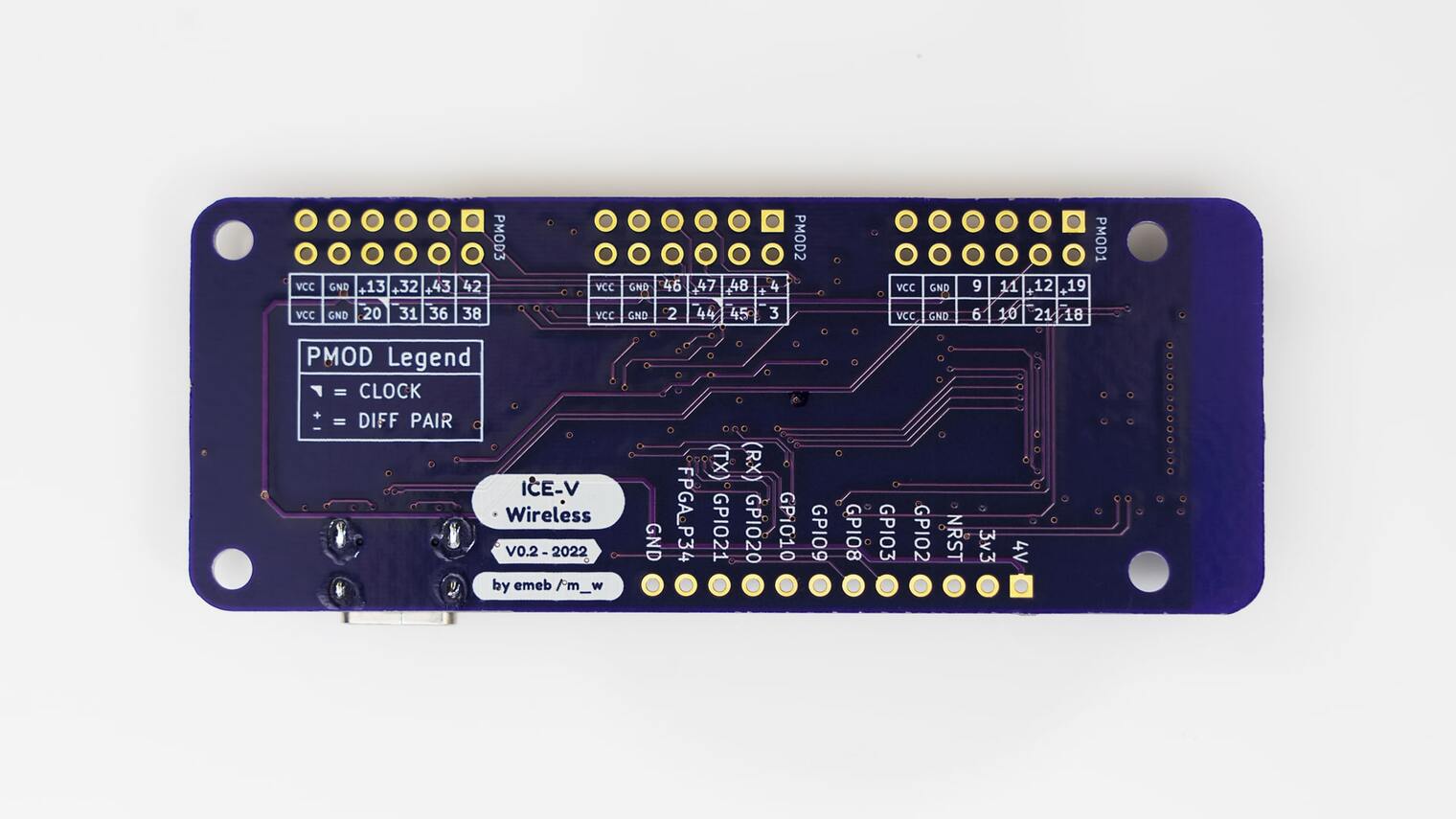
Fig. 210 ICE-V Wireless (Back)
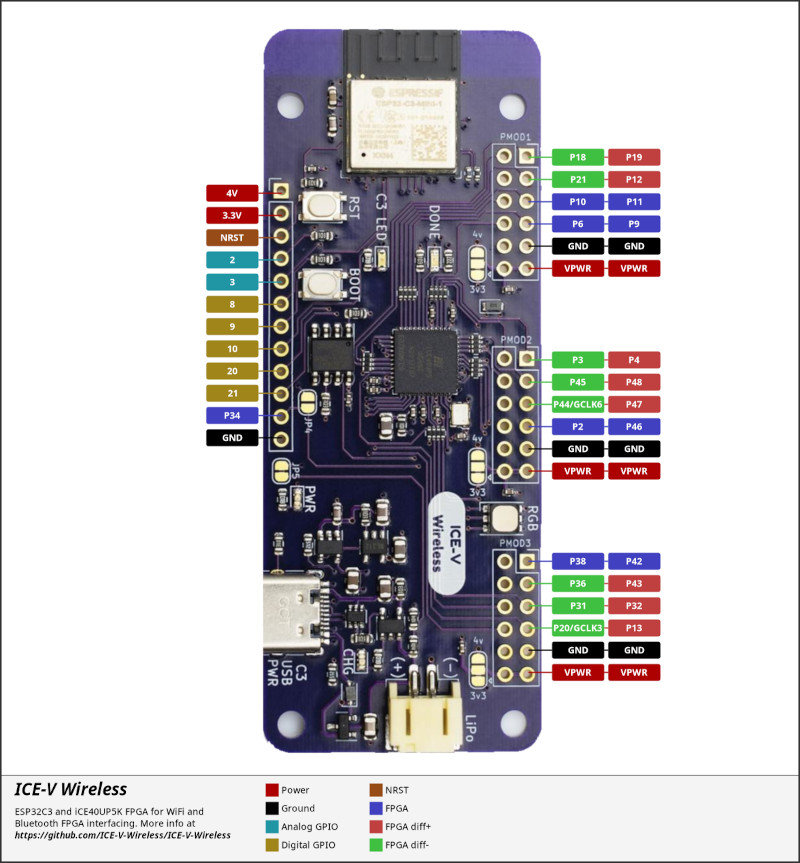
The J3 pins are 4V, 3.3V, NRST, GPIO2, GPIO3, GPIO8, GPIO9, GPIO10, GPIO20, GPIO21, FPGA_P34, and GND. Note that GPIO2 and GPIO3 may be configured for ADC operation.
For PMOD details, please refer to the PMOD Specification and the image below.
Programming and Debugging
Programming and debugging for the ICE-V Wireless ESP32-C3 target is incredibly easy 🎉 following the steps below.
Building and Flashing
For the Hello, world! application, follow the instructions below.
# From the root of the zephyr repository
west build -b icev_wireless samples/hello_world
west flash
Since the Zephyr console is by default on the usb_serial device, we use the espressif monitor to view.
$ west espressif monitor
Debugging
As with much custom hardware, the ESP32C3 modules require patches to OpenOCD that are not upstreamed. Espressif maintains their own fork of the project. The custom OpenOCD can be obtained by running the following extension:
west espressif install
Note
By default, the OpenOCD will be downloaded and installed under $HOME/.espressif/tools/zephyr directory (%USERPROFILE%/.espressif/tools/zephyr on Windows).
The Zephyr SDK uses a bundled version of OpenOCD by default. You can overwrite that behavior by adding the
-DOPENOCD=<path/to/bin/openocd> -DOPENOCD_DEFAULT_PATH=<path/to/openocd/share/openocd/scripts>
parameter when building.
Here is an example for building the Hello World application.
# From the root of the zephyr repository
west build -b icev_wireless samples/hello_world -- -DOPENOCD=<path/to/bin/openocd> -DOPENOCD_DEFAULT_PATH=<path/to/openocd/share/openocd/scripts>
west flash
You can debug an application in the usual way. Here is an example for the Hello World application.
# From the root of the zephyr repository
west build -b icev_wireless samples/hello_world
west debug