Bluetooth: Direct Test Mode
This sample enables the Direct Test Mode functions described in Bluetooth® Core Specification: Version 5.2, Vol. 6, Part F.
Requirements
The sample supports the following development kit:
Hardware platforms |
PCA |
Board name |
Build target |
|---|---|---|---|
PCA10095 |
|
||
PCA10112 |
|
Additionally, the sample requires one of the following testing devices:
Dedicated test equipment, like an Anritsu MT8852 tester. See Testing with a certified tester.
Another development kit with the same sample. See Testing with another development kit.
Another development kit connected to a PC with the Direct Test Mode sample available in the nRF Connect for Desktop. See Testing with nRF Connect for Desktop.
Overview
The sample uses Direct Test Mode (DTM) to test the operation of the following features of the radio:
Transmission power and receiver sensitivity
Frequency offset and drift
Modulation characteristics
Packet error rate
Intermodulation performance
Test procedures are defined in the document Bluetooth® Low Energy RF PHY Test Specification: Document number RF-PHY.TS.p15
You can carry out conformance tests using dedicated test equipment, such as the Anritsu MT8852 or similar, with an nRF5 running the DTM sample set as device under test (DUT).
DTM sample
The DTM sample includes two parts:
The DTM, Direct Test Mode library, which manages the nRF radio and controls the standard DTM procedures.
A sample that provides an external interface to the library.
You can find the source code of both parts here: samples/bluetooth/direct_test_mode/src.
The DTM sample contains a driver for a 2-wire UART interface. The driver maps two-octet commands and events to the DTM library, as specified by the Bluetooth Low Energy DTM specification.

The implementation is self-contained and requires no Bluetooth Low Energy protocol stack for its operation.
The MPU is initialized in the standard way.
The DTM library function dtm_init configures all interrupts, timers, and the radio.
main.c may be replaced with other interface implementations, such as an HCI interface, USB, or another interface required by the Upper Tester.
The interface to the Lower Tester uses the antenna connector of the chosen development kit. While in principle an aerial connection might be used, conformance tests cover the reading of the transmission power delivered by the DUT. For this reason, a coaxial connection between the DUT and the Lower Tester is employed for all conformance testing.
DTM module interface
The DTM function dtm_cmd_put implements the four commands defined by the Bluetooth Low Energy standard:
TEST SETUP(calledRESETin Bluetooth 4.0)RECEIVER_TESTTRANSMITTER_TESTTEST_END
In the dtm_cmd_put interface, DTM commands are accepted in the 2-byte format.
Parameters such as: CMD code, Frequency, Length, or Packet Type are encoded within this command.
The following DTM events are polled using the dtm_event_get function:
PACKET_REPORTING_EVENTTEST_STATUS_EVENT[SUCCESS|FAIL]

Supported PHYs
The DTM sample supports all four PHYs specified in DTM, but not all devices support all the PHYs.
PHY |
nRF5340 |
|---|---|
LE 1M |
Yes |
LE 2M |
Yes |
LE Coded S=8 |
Yes |
LE Coded S=2 |
Yes |
Bluetooth Direction Finding support
The DTM sample supports all Bluetooth Direction Finding modes specified in DTM.
Direction Finding mode |
nRF5340 |
|---|---|
AoD 1 us slot |
Yes |
AoD 2 us slot |
Yes |
AoA |
Yes |
The following antenna switching patterns are possible:
1, 2, 3, …, N
1, 2, 3, …, N, N - 1, N - 2, …, 1
The application supports a maximum of 19 antennas in the direction finding mode. The RADIO can control up to 8 GPIO pins for the purpose of controlling the external antenna switches used in direction finding.
Antenna matrix configuration
To use this sample to test the Bluetooth Direction Finding feature, additional configuration of GPIOs is required to control the antenna array.
An example of such configuration is provided in a devicetree overlay file nrf5340dk_nrf5340_cpunet.overlay.
The overlay file provides the information about of the GPIOs to be used by the Radio peripheral to switch between antenna patches during the Constant Tone Extension (CTE) reception or transmission. At least one GPIO must be provided to enable antenna switching.
The GPIOs are used by the radio peripheral in order given by the dfegpio#-gpios properties.
The order is important because it affects the mapping of the antenna switching patterns to GPIOs (see Antenna patterns).
To test Direction Finding, provide the following data related to antenna matrix design:
GPIO pins to
dfegpio#-gpiosproperties in thenrf5340dk_nrf5340_cpunet.overlayfile.The default antenna to be used to receive the PDU
dfe-pdu-antennaproperty in thenrf5340dk_nrf5340_cpunet.overlayfile.
Note
The PDU antenna is also used for the reference period transmission and reception.
Antenna patterns
The antenna switching pattern is a binary number where each bit is applied to a particular antenna GPIO pin.
For example, the pattern 0x3 means that antenna GPIOs at index 0,1 is set, while the next ones are left unset.
This also means that, for example, when using four GPIOs, the pattern count cannot be greater than 16 and the maximum allowed value is 15.
If the number of switch-sample periods is greater than the number of stored switching patterns, the radio loops back to the first pattern.
The following table presents the patterns that you can use to switch antennas on the Nordic-designed antenna matrix:
Antenna |
PATTERN[3:0] |
|---|---|
ANT_12 |
0 (0b0000) |
ANT_10 |
1 (0b0001) |
ANT_11 |
2 (0b0010) |
RFU |
3 (0b0011) |
ANT_3 |
4 (0b0100) |
ANT_1 |
5 (0b0101) |
ANT_2 |
6 (0b0110) |
RFU |
7 (0b0111) |
ANT_6 |
8 (0b1000) |
ANT_4 |
9 (0b1001) |
ANT_5 |
10 (0b1010) |
RFU |
11 (0b1011) |
ANT_9 |
12 (0b1100) |
ANT_7 |
13 (0b1101) |
ANT_8 |
14 (0b1110) |
RFU |
15 (0b1111) |
nRF21540 front-end module
You can add support for the nRF21540 front-end module (FEM) to the sample.
To add support for the nRF21540 FEM, build the sample for a board containing nRF21540 FEM like nrf21540dk_nrf52840 or create a devicetree overlay file describing how FEM is connected to nRF5 SoC in your device.
Note
If you use the nRF21540 EK, append nrf21540_ek shield to your build command instructing build system to append the appropriate devicetree overlay file.
If you use the nRF21540 DK, build your application for the nrf21540dk_nrf52840 board.
The devicetree for the nRF21540 DK already contains the required FEM configuration, so you do not need to set an additional build option.
For example, to build the sample from the command line for an nRF5340 DK with an attached nRF21540 EK, invoke the following command within the sample directory:
west build -b nrf5340dk_nrf5340_cpunet -- -DSHIELD=nrf21540_ek
Note
The nRF5340 DK network core peripherals, like UART and SPI, share an ID and a base address. To configure the nRF21540 front-end module gain, write the gain value over the SPI. In samples, UART is used as a control interface or shell transport. To send the gain value UART is temporary disabled and restarted after the SPI transfer.
For more details refer to the following documentation:
You can configure the transmitted power gain, antenna output and activation delay in nRF21540 using vendor-specific commands, see Vendor-specific packet payload.
Skyworks front-end module
The Skyworks SKY66114 and SKY66403 are front-end module (FEM) devices that support the 2-pin PA/LNA interface. You can also use other Skyworks FEM devices that provide the same hardware interface.
To use the generic FEM implementation with Skyworks front-end modules refer to Adding support for Skyworks front-end module for details.
Use case of incomplete physical connections to the FEM module
The devicetree configuration allows you to use a minimal pin configuration.
Connect all unused pins to the fixed logic level as instructed in the official documentation.
For example csd-gpios is an optional pin that sets the device into sleep mode.
If this pin is not controlled by the driver, it must be connected to the fixed logic level.
You can configure the antenna output and activation delay for the Skyworks front-end module (FEM) using vendor-specific commands, see Vendor-specific packet payload.
Vendor-specific packet payload
The Bluetooth Low Energy 2-wire UART DTM interface standard reserves the Packet Type, also called payload parameter, with binary value 11 for a Vendor Specific packet payload.
The DTM command is interpreted as a vendor-specific one when both the following conditions are met:
Its CMD field is set to Transmitter Test, binary
10.Its PKT field is set to vendor-specific, binary
11.
Vendor specific commands can be divided into different categories as follows:
If the Length field is set to
0(symbolCARRIER_TEST), an unmodulated carrier is turned on at the channel indicated by the Frequency field. It remains turned on until aTEST_ENDorRESETcommand is issued.If the Length field is set to
1(symbolCARRIER_TEST_STUDIO), this field value is used by the nRFgo Studio to indicate that an unmodulated carrier is turned on at the channel. It remains turned on until aTEST_ENDorRESETcommand is issued.If the Length field is set
2(symbolSET_TX_POWER), the Frequency field sets the TX power in dBm. The valid TX power values are specified in the product specification ranging from -40 to +4, where 0 dBm is the reset value. Only the 6 least significant bits will fit in the Length field. The two most significant bits are calculated by the DTM module. This is possible because the 6 least significant bits of all valid TX power values are unique. The TX power can be modified only when no Transmitter Test or Receiver Test is running.If the Length field is set to
3(symbolFEM_ANTENNA_SELECT), the Frequency field sets the front-end module (FEM) antenna output. The valid values are:0 - ANT1 enabled, ANT2 disabled
1 - ANT1 disabled, ANT2 enabled
If the Length field is set to
4(symbolFEM_GAIN_SET), the Frequency field sets the front-end module (FEM) TX gain value in arbitrary units. The valid gain values are specified in your product-specific front-end module (FEM). For example, in the nRF21540 front-end module, the gain range is 0 - 31.If the Length field is set to
5(symbolFEM_ACTIVE_DELAY_SET), the Frequency field sets the front-end module (FEM) activation delay in microseconds relative to the radio start. By default, this value is set to (radio ramp-up time - front-end module (FEM) TX/RX settling time).If the Length field is set to
6(symbolFEM_DEFAULT_PARAMS_SET) and the Frequency field to any value, the front-end module parameters, such as antenna output, gain, and delay, are set to their default values.All other values of Frequency and Length field are reserved.
Note
Front-end module configuration parameters, such as antenna output, gain, and active delay, are not set to their default values after the DTM reset command. Testers, for example Anritsu MT885, issue a reset command in the beginning of every test. Therefore, you cannot run automated test scripts for front-end modules with other than the default parameters.
If you have changed the default parameters of the front-end module, you can restore them.
You can either send the FEM_DEFAULT_PARAMS_SET command or power cycle the front-end module.
The DTM-to-Serial adaptation layer
main.c is an implementation of the UART interface specified in the Bluetooth Core Specification: Vol. 6, Part F, Chap. 3.
The default selection of UART pins is defined in zephyr/boards/arm/board_name/board_name.dts.
You can change the defaults using the symbols tx-pin and rx-pin in the DTS overlay file at the project level.
Debugging
In this sample, the UART console is used to exchange commands and events defined in the DTM specification. Debug messages are not displayed in this UART console. Instead, they are printed by the RTT logger.
If you want to view the debug messages, follow the procedure in Connecting using RTT. For more information about debugging in the nRF Connect SDK, see Debugging an application.
Building and running
This sample can be found under samples/bluetooth/direct_test_mode in the nRF Connect SDK folder structure.
To build the sample with Visual Studio Code, follow the steps listed on the Building nRF Connect SDK application quick guide page in the nRF Connect for VS Code extension documentation. See Building and programming an application for other building and programming scenarios and Testing and debugging an application for general information about testing and debugging in the nRF Connect SDK.
Note
On the nRF5340 development kit, the Direct Test Mode sample is a standalone network sample.
It does not require any counterpart application sample.
However, you must still program the application core to boot up the network core.
You can use any sample for this, for example, the nRF5340: Empty firmware for application core.
The nRF5340: Empty firmware for application core is built and programmed automatically by default.
If you want to program another sample for the application core, unset the CONFIG_NCS_SAMPLE_EMPTY_APP_CORE_CHILD_IMAGE option.
Testing
After programming the sample to your development kit, you can test it in the three following ways.
Note
For the nRF5340 DK board (PCA10095), see Getting logging output for information about the COM terminals on which the logging output is available.
Testing with a certified tester
Conformance testing is done using a certified tester. The setup depends on the tester used, and details about the test operation must be found in the tester documentation.
Application note nAN34 describes two alternatives for setting up a production test with DTM using one of our old devices.
Testing with another development kit
Connect both development kits to the computer using a USB cable. The computer assigns to the development kit a COM port on Windows or a ttyACM device on Linux, which is visible in the Device Manager.
Connect to both kits with a terminal emulator. See Direct Test Mode terminal connection for the required settings.
Start
TRANSMITTER_TESTby sending the0x80 0x96DTM command to one of the connected development kits. This command will trigger TX activity on the 2402 MHz frequency (1st channel) with10101010packet pattern and 37-byte packet length.Observe that you received the
TEST_STATUS_EVENTpacket in response with the SUCCESS status field:0x00 0x00.Start
RECEIVER_TESTby sending the0x40 0x96DTM command to the second development kit. Command parameters are identical to the ones used for theTRANSMITTER_TESTcommand.Observe that you received the
TEST_STATUS_EVENTpacket in response with the SUCCESS status field:0x00 0x00.Finish RX testing using the
TEST_END DTMcommand by sending the0xC0 0x00packet.Observe that you received the
PACKET_REPORTING_EVENTpacket in response. For example, the0xD6 0xACmessage indicates that 22188 Radio packets have been received.Experiment with other combinations of commands and their parameters.
Testing with nRF Connect for Desktop
Connect the kit to the computer using a USB cable. The kit is assigned a COM port (Windows) or ttyACM device (Linux), which is visible in the Device Manager.
Connect to the kit with a terminal emulator (for example, PuTTY). See How to connect with PuTTY for the required settings. See Direct Test Mode terminal connection for the required settings.
Start the
TRANSMITTER_TESTby sending the0x80 0x96DTM command to the connected development kit. This command triggers TX activity on 2402 MHz frequency (1st channel) with10101010packet pattern and 37-byte packet length.Observe that you received the
TEST_STATUS_EVENTpacket in response with the SUCCESS status field:0x00 0x00.Start the Direct Test Mode application in nRF Connect for Desktop and select the development kits to communicate with.
Set the Receiver mode and 37th channel in the test configuration menu.
Start the test.
On the application chart, observe that the number of RX packets is increasing for the 2402 MHz channel.
Stop the test.
Swap roles. Set the application to the RX mode and the connected development kit to the TX mode.
Direct Test Mode terminal connection
To send commands to and receive responses from the development kit that runs the Direct Test Mode sample, connect to it with RealTerm in Windows or Minicom in Linux.
The Bluetooth Low Energy DTM UART interface standard specifies the following configuration:
Eight data bits
No parity
One stop bit
No hardware flow control
A selection of bit rates from 9600 to 1000000, one of which must be supported by the DUT. It might be possible to run other bit rates by experimenting with parameters.
Note
The default bit rate of the DTM UART driver is 19200 bps, which is supported by most certified testers.
You must send all commands as two-byte HEX numbers. The responses must have the same format.
Connect with RealTerm (Windows)
The RealTerm terminal program offers a graphical interface for setting up your connection.
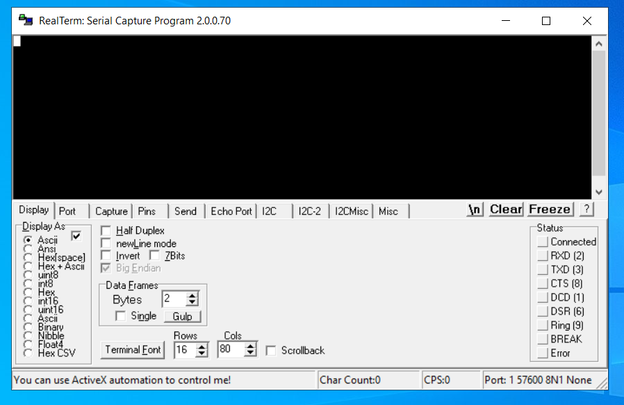
The RealTerm start window
To test DTM with RealTerm, complete the following steps:
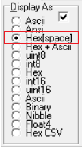
On the Display tab, set Display As to Hex[space].
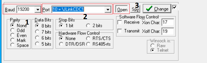
Open the Port tab and configure the serial port parameters:
Set the Baud to
19200(1).Select your J-Link serial port from the Port list (2).
Set the port status to
Open(3).
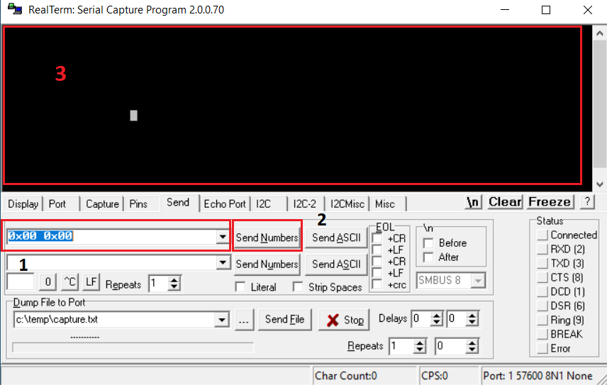
Open the Send tab:
Write the command as a hexadecimal number in the field (1). For example, write
0x00 0x00to send a Reset command.Click the Send Numbers button (2) to send the command.
Observe the response in the DTM in area (3). The response is encoded as hexadecimal numbers.
Connect with Minicom (Linux)
Minicom is a serial communication program that connects to the DTM device.
On the Linux operating system, install a Minicom terminal. On Ubuntu, run:
sudo apt-get install minicom
Run the Minicom terminal:
sudo minicom -D DTM serial port -s
For example:
sudo minicom -D /dev/serial/by-id/usb-SEGGER_J-Link_000683580193-if00 -sThe -s option switches you to Minicom setup mode.
Configure the Minicom terminal:
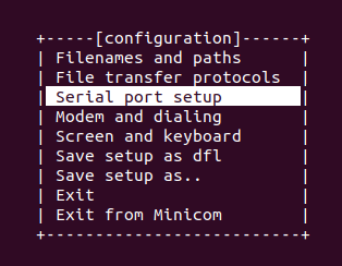
Configuration window
Select Serial port setup and set UART baudrate to
19200.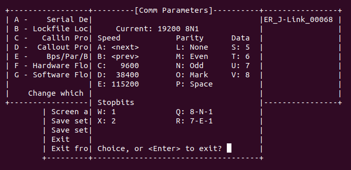
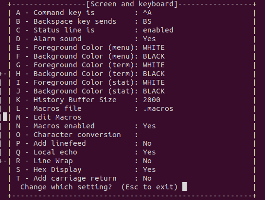
Select Screen and keyboard and press S on the keyboard to enable the Hex Display.
Press Q on the keyboard to enable Local echo.
Minicom is now configured for receiving data. However, you cannot use it for sending DTM commands.
Send DTM commands:
To send DTM commands, use
echowith-neoptions in another terminal. You must encode the data as hexadecimal numbers (xHH, byte with hexadecimal value HH, 1 to 2 digits).sudo echo -ne "encoded command" > DTM serial port
To send a Reset command, for example, run the following command:
sudo echo -ne "\x00\x00" > /dev/serial/by-id/usb-SEGGER_J-Link_000683580193-if00
Dependencies
This sample uses the following nrfx dependencies:
nrfx/drivers/include/nrfx_timer.h
nrfx/hal/nrf_nvmc.h
nrfx/hal/nrf_radio.h
nrfx/helpers/nrfx_gppi.h
In addition, it uses the following Zephyr libraries:
-
drivers/clock_control.hdrivers/uart.h