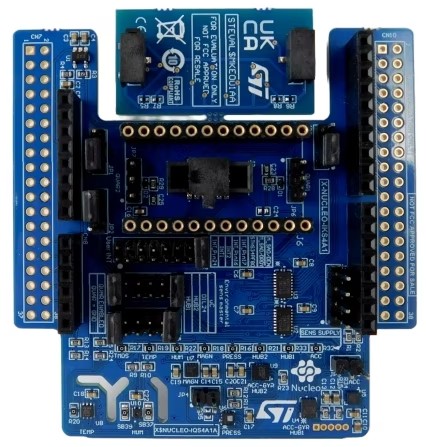
X-NUCLEO-IKS4A1: MEMS Inertial and Environmental Multi sensor shield
Overview
The X-NUCLEO-IKS4A1 is a motion MEMS and environmental sensor expansion board for the STM32 Nucleo. It is equipped with Arduino UNO R3 connector layout, and allows application development with features like sensor HUB (LSM6DSO16IS and LSM6DSV16X), camera module integration and Qvar touch/swipe gestures (thanks to the equipped electrode).

More general information about the board can be found at the X-NUCLEO-IKS4A1 website.
Hardware Description
X-NUCLEO-IKS4A1 provides the following key features:
LSM6DSO16IS: MEMS 3D accelerometer (±2/±4/±8/±16 g) + 3D gyroscope (±125/±250/±500/±1000/±2000 dps) with ISPU (Intelligent Processing Unit)
LIS2MDL: MEMS 3D magnetometer (±50 gauss)
LIS2DUXS12: Ultra low-power MEMS 3D accelerometer (±2/±4/±8/±16 g) with Qvar, AI, & anti-aliasing
LPS22DF: Low-power and high-precision MEMS pressure sensor, 260-1260 hPa absolute digital output barometer
SHT40AD1B: High-accuracy, ultra-low-power relative humidity and temperature sensor (by Sensirion)
STTS22H: Low-voltage, ultralow-power, 0.5 °C accuracy temperature sensor (–40 °C to +125 °C)
LSM6DSV16X: MEMS 3D accelerometer (±2/±4/±8/±16 g) + 3D gyroscope (±125/±250/±500/±1000/±2000/±4000 dps) with embedded sensor fusion, AI, Qvar
DIL 24-pin socket available for additional MEMS adapters and other sensors
Free comprehensive development firmware library and example for all sensors compatible with STM32Cube firmware
Equipped with Qvar touch/swipe electrode
I²C sensor hub features on LSM6DSO and LSM6DSV16X available
MIPI I3C® compatibility for communication with LIS2DUXS12, LSM6DSV16X and LPS22DF
Compatible with STM32 Nucleo boards
Equipped with Arduino UNO R3 connector
Equipped with industrial connector for IR sensor (STHS34PF80) application development. It can be connected at the same time of external MEMS through DIL24 adapter
Available interface for external camera module applications coupled with LSM6DSV16X through aux SPI (3/4 w)
RoHS compliant
WEEE compliant
UKCA compliant
Hardware Configuration
X-NUCLEO-IKS4A1 board can be configured in five different modes, which can be selected through J4 and J5 jumpers. Additional information about X-NUCLEO-IKS4A1 configuration modes and how sensors are connected together can be found in the X-NUCLEO-IKS4A1 user manual
Mode 1: Standard Mode
In standard I2C mode, all devices are connected to an external main board via the same I2C bus.
The board configuration is:
J4: 1-2, 11-12 (STM_SDA = SENS_SDA, HUB_SDx = GND)
J5: 1-2, 11-12 (STM_SCL = SENS_SCL, HUB_SCx = GND)
Mode 2: LSM6DSO16IS SensorHub Mode (SHUB2)
In this sensor hub I2C mode, it is possible to power-up the 6-axes IMU (Inertial Measurement Unit) functionalities by collecting external data through a direct control of the on-board environmental sensors (temperature, pressure and magnetometer) and external sensor (DIL24) through the auxiliary I2Cz bus “SENS_I2C”. LSM6DSV16X, LIS2DUXS12 and SHT40AD1B remains connected to the main bus “uC_I2C” coming from the external board.
The board configuration is:
J4: 7-8 (HUB2_SDx = SENS_SDA)
J5: 7-8 (HUB2_SCx = SENS_SCL)
Mode 3: LSM6DSV16X SensorHub Mode (SHUB1)
In this sensor hub, it is possible to power-up the 6-axes IMU (Inertial Measurement Unit) functionalities by collecting external data through a direct control of the on-board environmental sensors (temperature, pressure and magnetometer) and external sensor (DIL24) through the auxiliary I2C bus “SENS_I2C”. LSM6DSO16IS, LIS2DUXS12 and SHT40AD1B remains connected to the main bus “uC_I2C” coming from the external board.
The board configuration is:
J4: 5-6 (HUB1_SDx = SENS_SDA)
J5: 5-6 (HUB1_SDx = SENS_SDA)
Mode 4: DIL24 SensorHub Mode
In case a sensor with sensor hub embedded functionality is mounted to the board through DIL24 adapter, it is possible to exploit this functionality as for LSM6DSO16IS and the LSM6DSV16X. In this configuration, may be necessary to connect the DIL24 to the external board through SPI lines in order to avoid an address conflict on I2C bus with the LSM6DSO16IS and the LSM6DSV16X. This is done by changing the SBx configuration.
The board configuration is:
J4: 9-10 (DIL_SDx = SENS_SDA)
J5: 9-10 (DIL_SDx = SENS_SDA)
Mode 5: LSM6DSO16IS as Qvar controller
In this configuration, it is possible to use the equipped Qvar swipe electrode (by plugging it on JP6 and JP7 connectors) through the LSM6DSO16IS.
The board configuration is:
J4: 3-4 (HUB1_SDx = QVAR1)
J5: 3-4 (HUB1_Scx = QVAR2)
Devicetree Overlays
There are three predefined DT overlays in the board:
boards/shields/x_nucleo_iks4a1/x_nucleo_iks4a1.overlay This overlay describes sensor connections (and matching h/w configuration to be done) as explained in Standard Mode (Mode 1: Standard Mode)
boards/shields/x_nucleo_iks4a1/x_nucleo_iks4a1_shub1.overlay This overlay describes sensor connections (and matching h/w configuration to be done) as explained in SHUB1 Mode (Mode 3: LSM6DSV16X SensorHub Mode (SHUB1))
boards/shields/x_nucleo_iks4a1/x_nucleo_iks4a1_shub2.overlay This overlay describes sensor connections (and matching h/w configuration to be done) as explained in SHUB2 Mode (Mode 2: LSM6DSO16IS SensorHub Mode (SHUB2))
Examples
Three samples are provided as examples for x-nucleo-iks4a1 shield, each one associated
with one of the overlays described above:
X-NUCLEO-IKS4A1 shield Standard (Mode 1) sample application, to be used when the shield is configured in Standard Mode (Mode 1)
X-NUCLEO-IKS4A1 shield SHUB1 (Mode 3) sample application, to be used when the shield is configured in SHUB1 Mode (Mode 3)
X-NUCLEO-IKS4A1: shield SHUB2 (Mode 2) sample application, to be used when the shield is configured in SHUB2 Mode (Mode 2)
See also Shields for more details.
