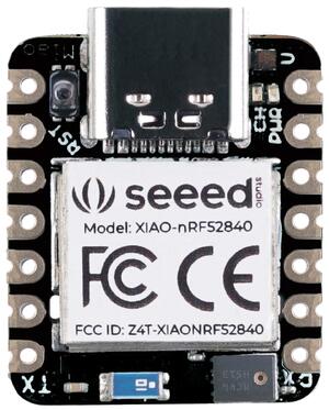
XIAO BLE (Sense)
Overview
The Seeed XIAO BLE (Sense) is a tiny (21 mm x 17.5 mm) Nordic Semiconductor nRF52840 ARM Cortex-M4F development board with onboard LEDs, USB port, QSPI flash, battery charger, and range of I/O broken out into 14 pins.

Hardware
Nordic nRF52840 Cortex-M4F processor at 64MHz
2MB QSPI Flash
RGB LED
USB Type-C Connector, nRF52840 acting as USB device
Battery charger BQ25101
Reset button
Bluetooth antenna
LSM6DS3TR-C 6D IMU (3D accelerometer and 3D gyroscope) (XIAO BLE Sense only)
PDM microphone (XIAO BLE Sense only)
Supported Features
The xiao_ble board configuration supports the following hardware features:
Interface |
Controller |
Driver/Component |
|---|---|---|
ADC |
on-chip |
adc |
CLOCK |
on-chip |
clock_control |
FLASH |
on-chip |
flash, QSPI flash |
GPIO |
on-chip |
gpio |
I2C(M) |
on-chip |
i2c |
MPU |
on-chip |
arch/arm |
NVIC |
on-chip |
arch/arm |
PWM |
on-chip |
pwm |
RADIO |
on-chip |
Bluetooth, ieee802154 |
RTC |
on-chip |
system clock |
SPI(M/S) |
on-chip |
spi |
UART |
on-chip |
serial |
USB |
on-chip |
usb |
WDT |
on-chip |
watchdog |
Other hardware features have not been enabled yet for this board.
Connections and IOs
The XIAO BLE wiki [1] has detailed information about the board including pinouts [2] and the schematic [3].
LED
LED1 (red) = P0.26
LED2 (green) = P0.30
LED3 (blue) = P0.06
Programming and Debugging
The XIAO BLE ships with the Adafruit nRF52 Bootloader [5] which supports flashing using UF2 [6]. Doing so allows easy flashing of new images, but does not support debugging the device. For debugging please use External Debugger.
UF2 Flashing
To enter the bootloader, connect the USB port of the XIAO BLE to your host, and double tap the reset botton to the left of the USB connector. A mass storage device named XIAO BLE should appear on the host. Using the command line, or your file manager copy the zephyr/zephyr.uf2 file from your build to the base of the XIAO BLE mass storage device. The XIAO BLE will automatically reset and launch the newly flashed application.
External Debugger
In order to support debugging the device, instead of using the bootloader, you can use an External Debug Probe. To flash and debug Zephyr applications you need to use Seeeduino XIAO Expansion Board [4] or solder an SWD header onto the back side of the board.
For Segger J-Link debug probes, follow the instructions in the J-Link External Debug Probe page to install and configure all the necessary software.
Flashing
Follow the instructions in the J-Link External Debug Probe page to install and configure all the necessary software. Then build and flash applications as usual (see Building an Application and Run an Application for more details).
Here is an example for the Hello World application.
First, run your favorite terminal program to listen for output.
$ minicom -D <tty_device> -b 115200
Replace <tty_device> with the port where the board XIAO BLE
can be found. For example, under Linux, /dev/ttyACM0.
Then build and flash the application in the usual way. Just add
CONFIG_BOOT_DELAY=5000 to the configuration, so that USB CDC ACM is
initialized before any text is printed, as below:
# From the root of the zephyr repository
west build -b xiao_ble samples/hello_world -- -DCONFIG_BOOT_DELAY=5000
west flash
# From the root of the zephyr repository
west build -b xiao_ble_sense samples/hello_world -- -DCONFIG_BOOT_DELAY=5000
west flash
Debugging
Refer to the J-Link External Debug Probe page to learn about debugging boards with a Segger IC.
Testing the LEDs in the XIAO BLE (Sense)
There is a sample that allows to test that LEDs on the board are working properly with Zephyr:
# From the root of the zephyr repository
west build -b xiao_ble samples/basic/blinky
west flash
# From the root of the zephyr repository
west build -b xiao_ble_sense samples/basic/blinky
west flash
You can build and flash the examples to make sure Zephyr is running correctly on your board. The LED definitions can be found in boards/arm/xiao_ble/xiao_ble_common.dtsi.
Testing shell over USB in the XIAO BLE (Sense)
There is a sample that allows to test shell interface over USB CDC ACM interface with Zephyr:
# From the root of the zephyr repository
west build -b xiao_ble samples/subsys/shell/shell_module
west flash
# From the root of the zephyr repository
west build -b xiao_ble_sense samples/subsys/shell/shell_module
west flash
