Bluetooth Stack Architecture
Overview
This page describes the software architecture of Zephyr’s Bluetooth protocol stack.
Note
Zephyr supports mainly Bluetooth Low Energy (BLE), the low-power version of the Bluetooth specification. Zephyr also has limited support for portions of the BR/EDR Host. Throughout this architecture document we use BLE interchangeably for Bluetooth except when noted.
BLE Layers
There are 3 main layers that together constitute a full Bluetooth Low Energy protocol stack:
Host: This layer sits right below the application, and is comprised of multiple (non real-time) network and transport protocols enabling applications to communicate with peer devices in a standard and interoperable way.
Controller: The Controller implements the Link Layer (LE LL), the low-level, real-time protocol which provides, in conjunction with the Radio Hardware, standard-interoperable over-the-air communication. The LL schedules packet reception and transmission, guarantees the delivery of data, and handles all the LL control procedures.
Radio Hardware: Hardware implements the required analog and digital baseband functional blocks that permit the Link Layer firmware to send and receive in the 2.4GHz band of the spectrum.
Host Controller Interface
The Bluetooth Specification describes the format in which a Host must communicate with a Controller. This is called the Host Controller Interface (HCI) protocol. HCI can be implemented over a range of different physical transports like UART, SPI, or USB. This protocol defines the commands that a Host can send to a Controller and the events that it can expect in return, and also the format for user and protocol data that needs to go over the air. The HCI ensures that different Host and Controller implementations can communicate in a standard way making it possible to combine Hosts and Controllers from different vendors.
Configurations
The three separate layers of the protocol and the standardized interface make it possible to implement the Host and Controller on different platforms. The two following configurations are commonly used:
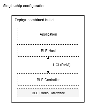
Single-chip configuration: In this configuration, a single microcontroller implements all three layers and the application itself. This can also be called a system-on-chip (SoC) implementation. In this case the BLE Host and the BLE Controller communicate directly through function calls and queues in RAM. The Bluetooth specification does not specify how HCI is implemented in this single-chip configuration and so how HCI commands, events, and data flows between the two can be implementation-specific. This configuration is well suited for those applications and designs that require a small footprint and the lowest possible power consumption, since everything runs on a single IC.
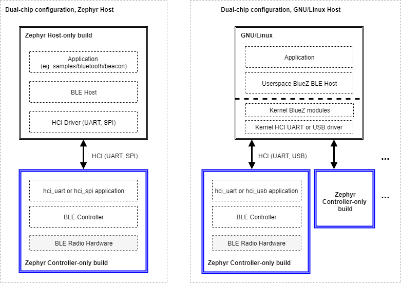
Dual-chip configuration: This configuration uses two separate ICs, one running the Application and the Host, and a second one with the Controller and the Radio Hardware. This is sometimes also called a connectivity-chip configuration. This configuration allows for a wider variety of combinations of Hosts when using the Zephyr OS as a Controller. Since HCI ensures interoperability among Host and Controller implementations, including of course Zephyr’s very own BLE Host and Controller, users of the Zephyr Controller can choose to use whatever Host running on any platform they prefer. For example, the host can be the Linux BLE Host stack (BlueZ) running on any processor capable of supporting Linux. The Host processor may of course also run Zephyr and the Zephyr OS BLE Host. Conversely, combining an IC running the Zephyr Host with an external Controller that does not run Zephyr is also supported.
Build Types
The Zephyr software stack as an RTOS is highly configurable, and in particular, the BLE subsystem can be configured in multiple ways during the build process to include only the features and layers that are required to reduce RAM and ROM footprint as well as power consumption. Here’s a short list of the different BLE-enabled builds that can be produced from the Zephyr project codebase:
Controller-only build: When built as a BLE Controller, Zephyr includes the Link Layer and a special application. This application is different depending on the physical transport chosen for HCI:
This application acts as a bridge between the UART, SPI or USB peripherals and the Controller subsystem, listening for HCI commands, sending application data and responding with events and received data. A build of this type sets the following Kconfig option values:
CONFIG_BT=yCONFIG_BT_LL_SW_SPLIT=y(if using the open source Link Layer)
Host-only build: A Zephyr OS Host build will contain the Application and the BLE Host, along with an HCI driver (UART or SPI) to interface with an external Controller chip. A build of this type sets the following Kconfig option values:
CONFIG_BT=y
All of the samples located in
samples/bluetoothexcept for the ones used for Controller-only builds can be built as Host-onlyCombined build: This includes the Application, the Host and the Controller, and it is used exclusively for single-chip (SoC) configurations. A build of this type sets the following Kconfig option values:
CONFIG_BT=yCONFIG_BT_LL_SW_SPLIT=y(if using the open source Link Layer)
All of the samples located in
samples/bluetoothexcept for the ones used for Controller-only builds can be built as Combined
The picture below shows the SoC or single-chip configuration when using a Zephyr combined build (a build that includes both a BLE Host and a Controller in the same firmware image that is programmed onto the chip):

Fig. 32 A Combined build on a Single-Chip configuration
When using connectivity or dual-chip configurations, several Host and Controller combinations are possible, some of which are depicted below:

Fig. 33 Host-only and Controller-only builds on dual-chip configurations
When using a Zephyr Host (left side of image), two instances of Zephyr OS must be built with different configurations, yielding two separate images that must be programmed into each of the chips respectively. The Host build image contains the application, the BLE Host and the selected HCI driver (UART or SPI), while the Controller build runs either the hci_uart, or the hci_spi app to provide an interface to the BLE Controller.
This configuration is not limited to using a Zephyr OS Host, as the right side of the image shows. One can indeed take one of the many existing GNU/Linux distributions, most of which include Linux’s own BLE Host (BlueZ), to connect it via UART or USB to one or more instances of the Zephyr OS Controller build. BlueZ as a Host supports multiple Controllers simultaneously for applications that require more than one BLE radio operating at the same time but sharing the same Host stack.
Source tree layout
The stack is split up as follows in the source tree:
subsys/bluetooth/hostThe host stack. This is where the HCI command and event handling as well as connection tracking happens. The implementation of the core protocols such as L2CAP, ATT, and SMP is also here.
subsys/bluetooth/controllerBluetooth Controller implementation. Implements the controller-side of HCI, the Link Layer as well as access to the radio transceiver.
include/bluetooth/Public API header files. These are the header files applications need to include in order to use Bluetooth functionality.
drivers/bluetooth/HCI transport drivers. Every HCI transport needs its own driver. For example, the two common types of UART transport protocols (3-Wire and 5-Wire) have their own drivers.
samples/bluetooth/Sample Bluetooth code. This is a good reference to get started with Bluetooth application development.
tests/bluetooth/Test applications. These applications are used to verify the functionality of the Bluetooth stack, but are not necessary the best source for sample code (see
samples/bluetoothinstead).doc/guides/bluetooth/Extra documentation, such as PICS documents.
Host
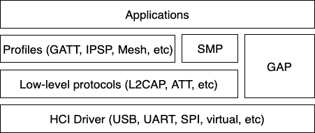
The Bluetooth Host implements all the higher-level protocols and profiles, and most importantly, provides a high-level API for applications. The following diagram depicts the main protocol & profile layers of the host.

Fig. 34 Bluetooth Host protocol & profile layers.
Lowest down in the host stack sits a so-called HCI driver, which is responsible for abstracting away the details of the HCI transport. It provides a basic API for delivering data from the controller to the host, and vice-versa.
Perhaps the most important block above the HCI handling is the Generic Access Profile (GAP). GAP simplifies Bluetooth LE access by defining four distinct roles of BLE usage:
Connection-oriented roles
Peripheral (e.g. a smart sensor, often with a limited user interface)
Central (typically a mobile phone or a PC)
Connection-less roles
Broadcaster (sending out BLE advertisements, e.g. a smart beacon)
Observer (scanning for BLE advertisements)
Each role comes with its own build-time configuration option:
CONFIG_BT_PERIPHERAL, CONFIG_BT_CENTRAL,
CONFIG_BT_BROADCASTER & CONFIG_BT_OBSERVER. Of the
connection-oriented roles central implicitly enables observer role, and
peripheral implicitly enables broadcaster role. Usually the first step
when creating an application is to decide which roles are needed and go
from there. Bluetooth mesh is a slightly special case, requiring at
least the observer and broadcaster roles, and possibly also the
Peripheral role. This will be described in more detail in a later
section.
Peripheral role
Most Zephyr-based BLE devices will most likely be peripheral-role
devices. This means that they perform connectable advertising and expose
one or more GATT services. After registering services using the
bt_gatt_service_register() API the application will typically
start connectable advertising using the bt_le_adv_start() API.
There are several peripheral sample applications available in the tree, such as samples/bluetooth/peripheral_hr.
Central role
Central role may not be as common for Zephyr-based devices as peripheral role, but it is still a plausible one and equally well supported in Zephyr. Rather than accepting connections from other devices a central role device will scan for available peripheral device and choose one to connect to. Once connected, a central will typically act as a GATT client, first performing discovery of available services and then accessing one or more supported services.
To initially discover a device to connect to the application will likely
use the bt_le_scan_start() API, wait for an appropriate device
to be found (using the scan callback), stop scanning using
bt_le_scan_stop() and then connect to the device using
bt_conn_le_create(). If the central wants to keep
automatically reconnecting to the peripheral it should use the
bt_le_set_auto_conn() API.
There are some sample applications for the central role available in the tree, such as samples/bluetooth/central_hr.
Observer role
An observer role device will use the bt_le_scan_start() API to
scan for device, but it will not connect to any of them. Instead it will
simply utilize the advertising data of found devices, combining it
optionally with the received signal strength (RSSI).
Broadcaster role
A broadcaster role device will use the bt_le_adv_start() API to
advertise specific advertising data, but the type of advertising will be
non-connectable, i.e. other device will not be able to connect to it.
Connections
Connection handling and the related APIs can be found in the Connection Management section.
Security
To achieve a secure relationship between two Bluetooth devices a process
called pairing is used. This process can either be triggered implicitly
through the security properties of GATT services, or explicitly using
the bt_conn_security() API on a connection object.
To achieve a higher security level, and protect against
Man-In-The-Middle (MITM) attacks, it is recommended to use some
out-of-band channel during the pairing. If the devices have a sufficient
user interface this “channel” is the user itself. The capabilities of
the device are registered using the bt_conn_auth_cb_register()
API. The bt_conn_auth_cb struct that’s passed to this API has
a set of optional callbacks that can be used during the pairing - if the
device lacks some feature the corresponding callback may be set to NULL.
For example, if the device does not have an input method but does have a
display, the passkey_entry and passkey_confirm callbacks would
be set to NULL, but the passkey_display would be set to a callback
capable of displaying a passkey to the user.
Depending on the local and remote security requirements & capabilities, there are four possible security levels that can be reached:
BT_SECURITY_L1No encryption and no authentication.
BT_SECURITY_L2Encryption but no authentication (no MITM protection).
BT_SECURITY_L3Encryption and authentication using the legacy pairing method from Bluetooth 4.0 and 4.1.
BT_SECURITY_L4Encryption and authentication using the LE Secure Connections feature available since Bluetooth 4.2.
Note
Mesh has its own security solution through a process called provisioning. It follows a similar procedure as pairing, but is done using separate mesh-specific APIs.
L2CAP
L2CAP stands for the Logical Link Control and Adaptation Protocol. It is a common layer for all communication over Bluetooth connections, however an application comes in direct contact with it only when using it in the so-called Connection-oriented Channels (CoC) mode. More information on this can be found in the L2CAP API section.
GATT
The Generic Attribute Profile is the most common means of communication over LE connections. A more detailed description of this layer and the API reference can be found in the GATT API reference section.
Mesh
Mesh is a little bit special when it comes to the needed GAP roles. By default, mesh requires both observer and broadcaster role to be enabled. If the optional GATT Proxy feature is desired, then peripheral role should also be enabled.
The API reference for mesh can be found in the Mesh API reference section.
LE Audio
The LE audio is a set of profiles and services that utilizes GATT and Isochronous Channel to provide audio over Bluetooth Low Energy. The architecture and API references can be found in Bluetooth Audio Architecture.
Persistent storage
The Bluetooth host stack uses the settings subsystem to implement persistent storage to flash. This requires the presence of a flash driver and a designated “storage” partition on flash. A typical set of configuration options needed will look something like the following:
CONFIG_BT_SETTINGS=y
CONFIG_FLASH=y
CONFIG_FLASH_PAGE_LAYOUT=y
CONFIG_FLASH_MAP=y
CONFIG_NVS=y
CONFIG_SETTINGS=y
Once enabled, it is the responsibility of the application to call settings_load() after having initialized Bluetooth (using the bt_enable() API).
Bluetooth Low Energy Controller
Hardware Requirements
Nordic Semiconductor
The Nordic Semiconductor Bluetooth Low Energy Controller implementation requires the following hardware peripherals.
Clock
A Low Frequency Clock (LFCLOCK) or sleep clock, for low power consumption between Bluetooth radio events
A High Frequency Clock (HFCLOCK) or active clock, for high precision packet timing and software based transceiver state switching with inter-frame space (tIFS) timing inside Bluetooth radio events
Real Time Counter (RTC)
1 instance
2 capture/compare registers
Timer
2 instances, one each for packet timing and tIFS software switching, respectively
7 capture/compare registers (3 mandatory, 1 optional for ISR profiling, 4 for single timer tIFS switching) on first instance
4 capture/compare registers for second instance, if single tIFS timer is not used.
Programmable Peripheral Interconnect (PPI)
21 channels (20 channels when not using pre-defined channels)
2 channel groups for software-based tIFS switching
Distributed Programmable Peripheral Interconnect (DPPI)
20 channels
2 channel groups for s/w tIFS switching
Software Interrupt (SWI)
3 instances, for Lower Link Layer, Upper Link Layer High priority, and Upper Link Layer Low priority execution
Radio
2.4 GHz radio transceiver with multiple radio standards such as 1 Mbps, 2 Mbps and Long Range Bluetooth Low Energy technology
Random Number Generator (RNG)
1 instance
AES electronic codebook mode encryption (ECB)
1 instance
Cipher Block Chaining - Message Authentication Code with Counter Mode encryption (CCM)
1 instance
Accelerated address resolver (AAR)
1 instance
GPIO
2 GPIO pins for PA and LNA, 1 each.
10 Debug GPIO pins (optional)
GPIO tasks and events (GPIOTE)
1 instance
1 channel for PA/LNA
Temperature sensor (TEMP)
For RC calibration
Interprocess Communication peripheral (IPC)
For HCI interface
UART
For HCI interface
